2 layers103 × 30.5 mm

 yotepanda/tomodachi
little panda guy
Tomodachi is an open-source printed circuit board by yotepanda, from the yotepanda/tomodachi repository on GitHub. It is a 2-layer board of 56 × 69.5 mm with 9 parts on 22 nets, routed with 82 tracks and 3 vias.
It belongs with the ESP32 and RISC-V boards of this library.
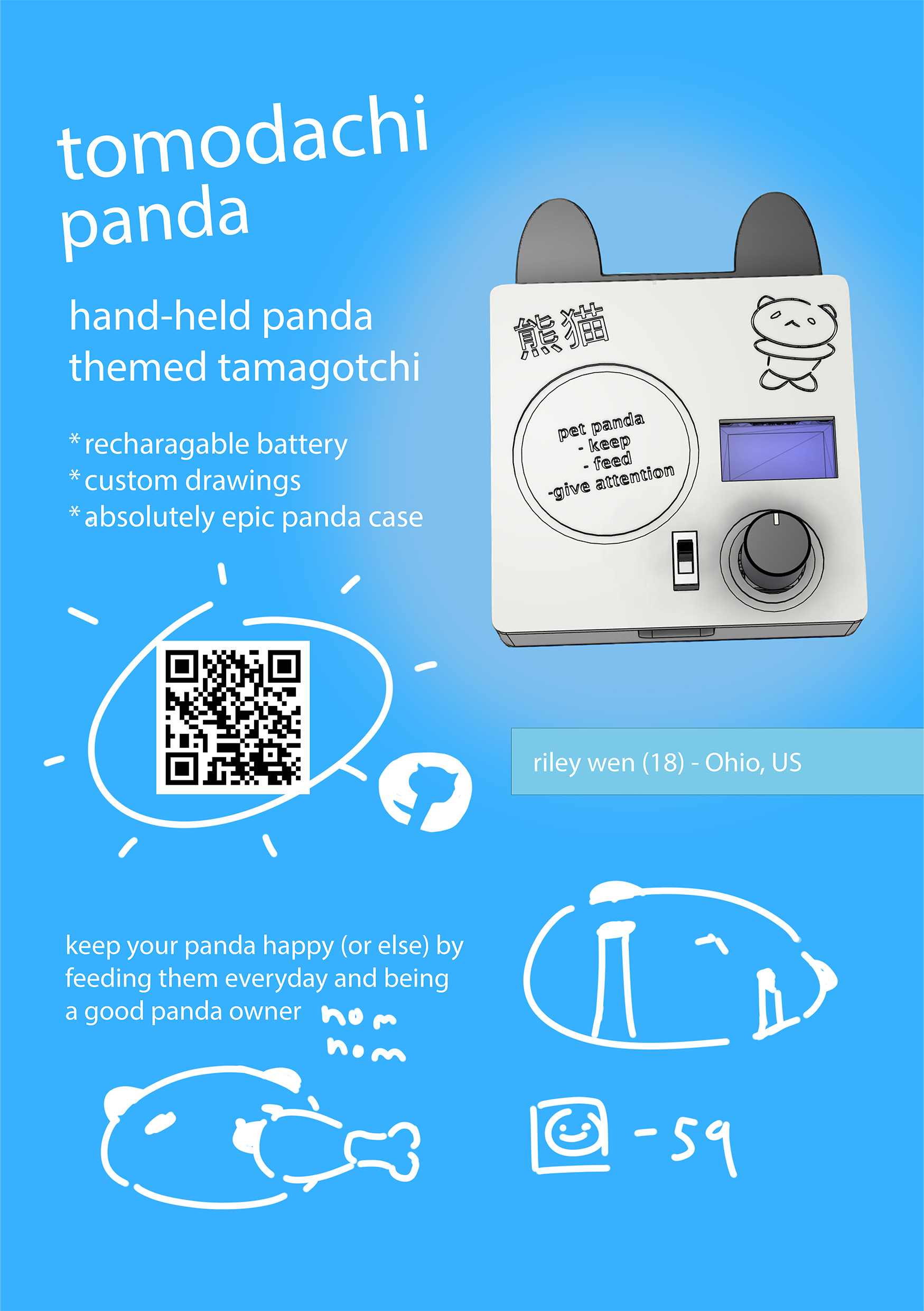
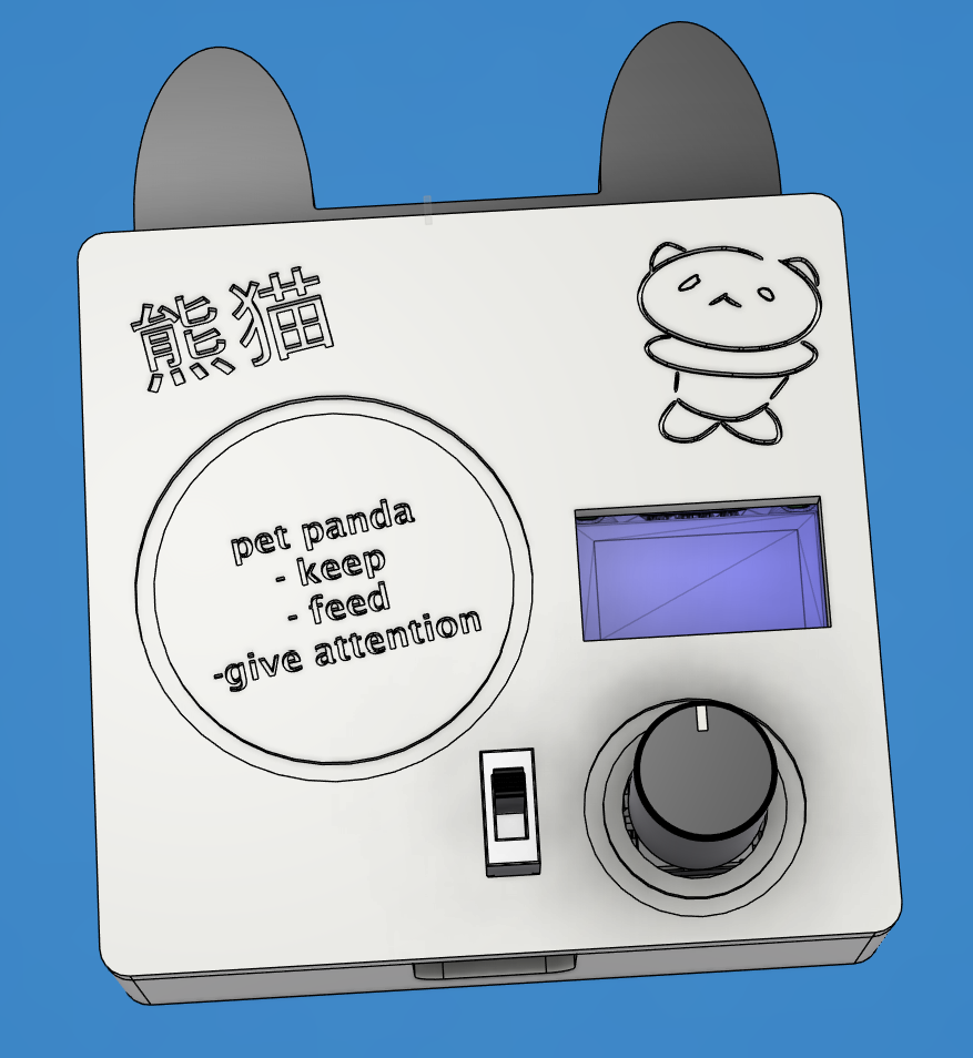
Tomodachi is a project to give you a heavily dependent and lazy panda to take care of, made because I need hardware and CAD design experience plus coding in firmware and also making panda themed gadgets is one of the coolest activities of all time
What the panda can do:
Features hand-drawn animations (more animations will come out once project is approed since I need the RTC to test more)
| Name | Quantity | Purchase link |
|---|---|---|
| ESP32C3 | 1 | XIAO ESP32C3 DIP link |
| DS3231 RTC | 1 | DS3231 RTC link |
| Coin battery (for RTC if not included) | 1 | Coin battery link |
| 0.96in SSD1306 (128x64) | 1 | SSD1306 (128x64) |
| TP4056 | 1 | TP4056 link |
| Shottky diodes | 2 | this was the cheapest & most appropriate I could find -> Schottky diodes link |
| KY-040 Rotary Encoder | 1 | KY-040 Rotary encoder link |
| SS12F44 Switch | 1 | SS12F44 Switch link |
| Battery 18650 3.7V | 1 | 18650 battery link |
| Wires |
(the material links were used assuming the fallout team has amazon prime for free shipping)
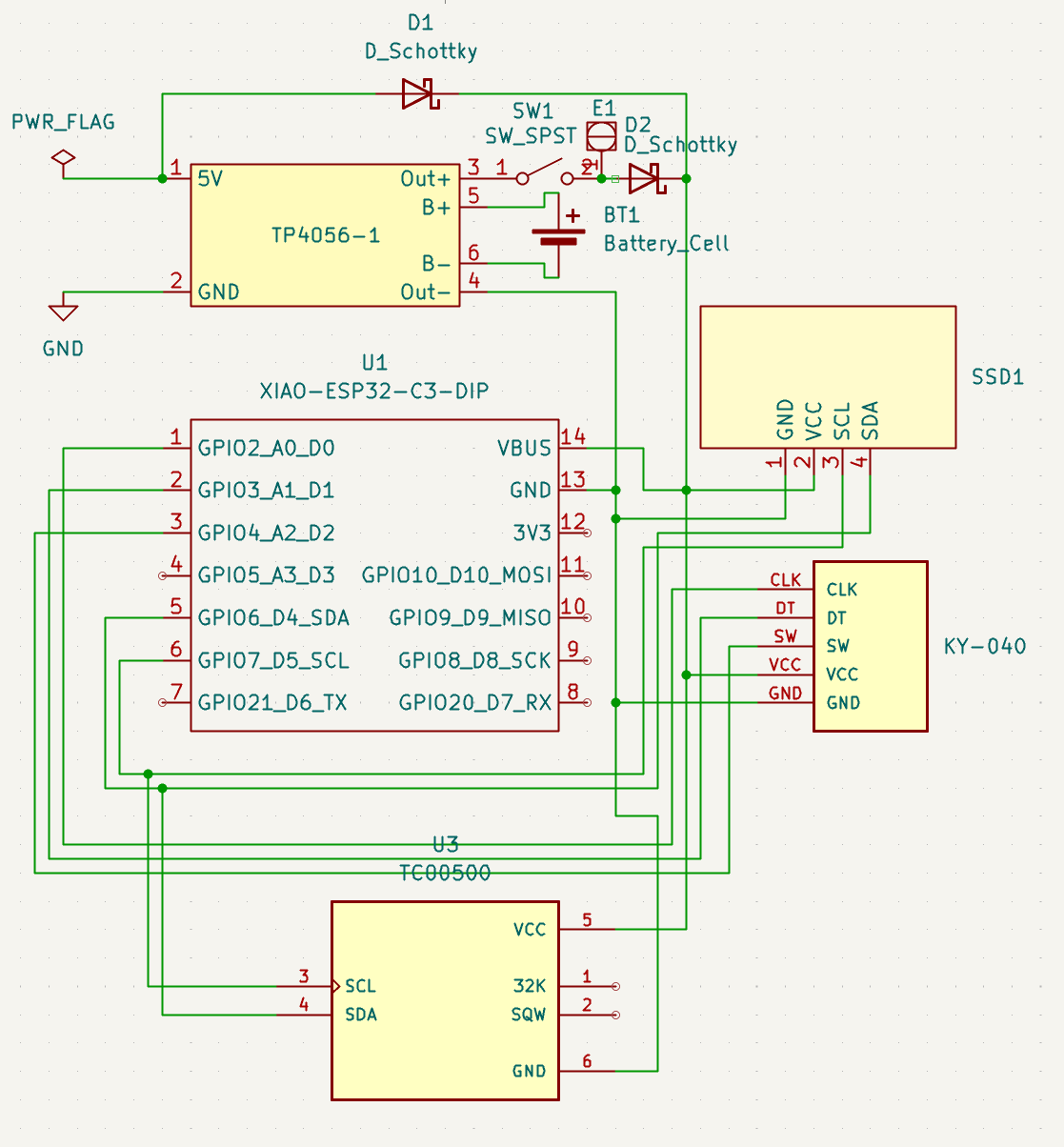 ^note that the part labeled E1 is because Kicad was mad I have the SS12F44 switch connected by wires instead of traces, please ignore
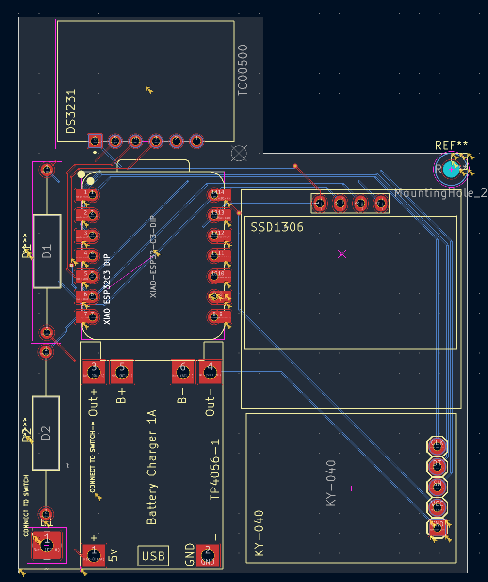
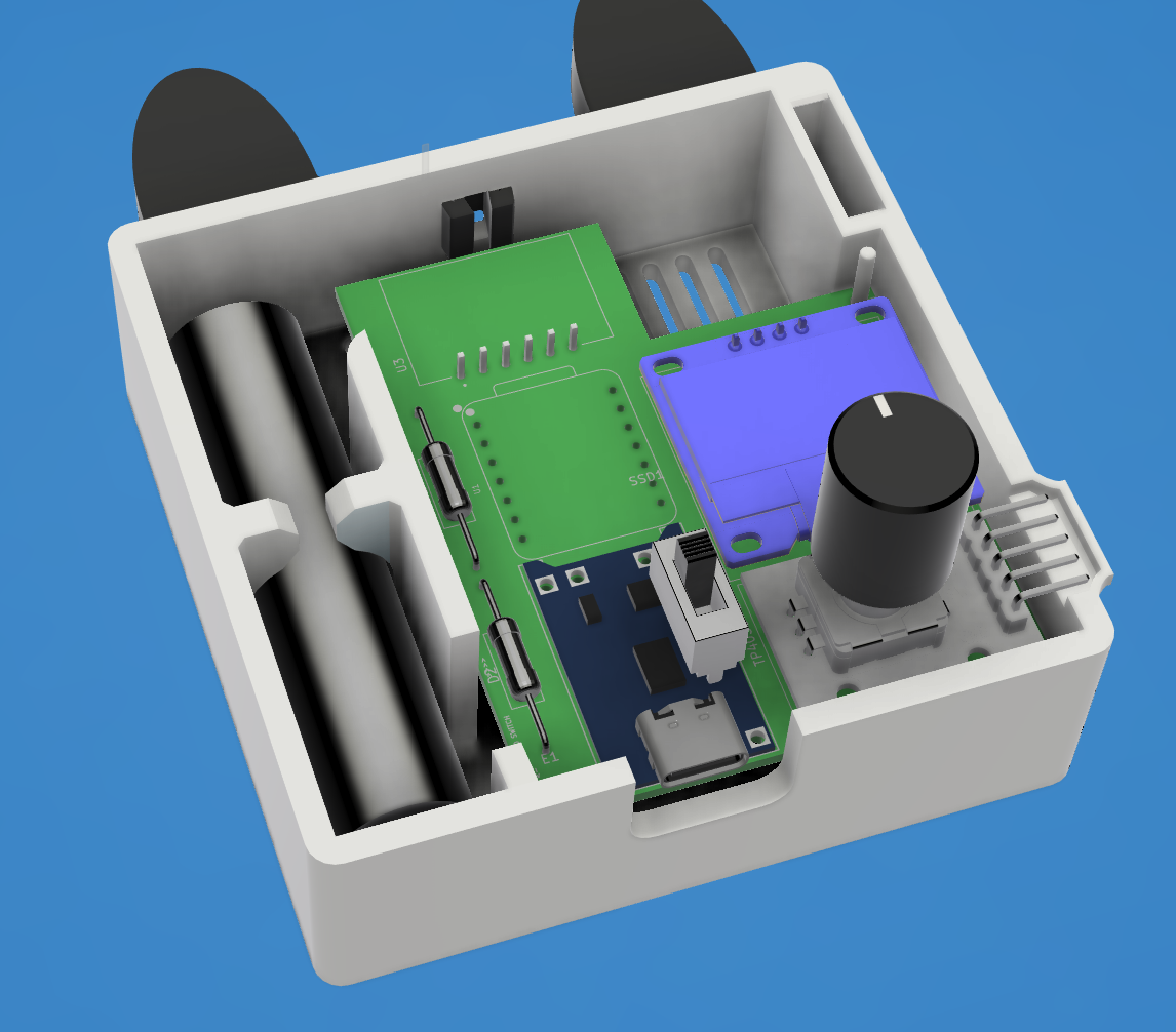
steps:
| Qty | Value | Footprint | References |
|---|---|---|---|
| 2 | D_Schottky | Resistor_THT:R_Axial_DIN0309_L9.0mm_D3.2mm_P20.32mm_Horizontal | D1, D2 |
| 1 | KY-040 | tomodachi:KY-040-PORT | KY-040 |
| 1 | TC00500 | tomodachi:MODULE_TC00500 | DS3231 |
| 1 | XIAO-ESP32-C3-DIP | tomodachi:XIAO-ESP32-C3-DIP | XIAO ESP32C3 DIP |
| 1 | ~ | tomodachi:TP4056-18650 | TP4056-1 |
| 1 | ~ | Connector_Wire:SolderWire-0.75sqmm_1x01_D1.25mm_OD3.5mm | E1 |
| 1 | ~ | tomodachi:SSD1306128x64OLED | SSD1306 |
The 8 most common of 9 parts.


FrameworkComputer/ExpansionCards
Reference designs and documentation to create Expansion Cards for the Framework Laptop

VoronDesign/Voron-Hardware
Cool Hardware designed by the Voron Design group

hackclub/OnBoard
💡 Join 1,000 teenagers and make your first PCB with a $100 grant!


adamws/kicad-kbplacer
KiCad plugin for automatic keyboard's key placement and routing
It measures 56 × 69.5 mm and has 2 copper layers, 1.6 mm thick.
9 parts. The full list of its parts is on this page, with links to each part's symbol and footprint where PCBKit's library has them.
From the yotepanda/tomodachi repository on GitHub, at the commit this page was made from: the board is src/cad/kicad/tomodachi.kicad_pcb and its schematic src/cad/kicad/tomodachi.kicad_sch. PCBKit opens the board in the browser, with nothing to install.
Its repository states no licence, so its author keeps all rights: ask yotepanda before reusing the design.