Skip to the content
2 layers56 × 69.5 mmTomodachi, the printed circuit board in 3D

little panda guy

Size
56 × 69.5 mm
Copper layers
2
Thickness
1.6 mm
Parts
9
Nets
22
Pads
55
Tracks, vias
82, 3
Routed
Yes
KiCad
KiCad 10.0 (file 20260206)
Created
8 May 2026
Updated
11 May 2026

Overview

Tomodachi is an open-source printed circuit board by yotepanda, from the yotepanda/tomodachi repository on GitHub. It is a 2-layer board of 56 × 69.5 mm with 9 parts on 22 nets, routed with 82 tracks and 3 vias.

It belongs with the ESP32 and RISC-V boards of this library.

README

README.md

tomodachi

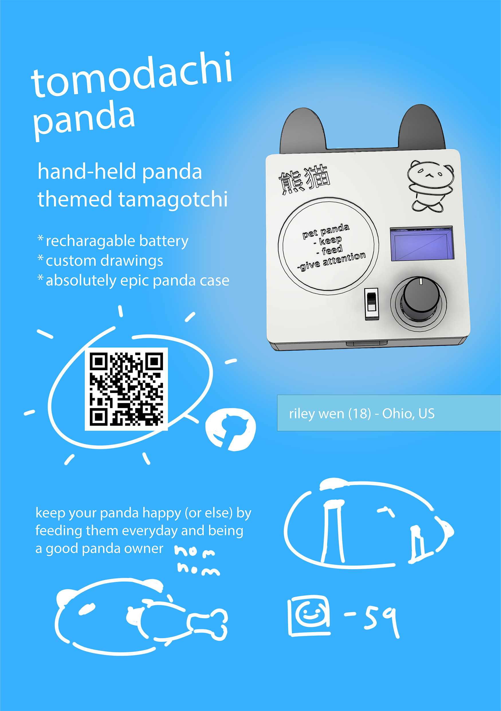
zine poster of the panda project

Tomodachi is a project to give you a heavily dependent and lazy panda to take care of, made because I need hardware and CAD design experience plus coding in firmware and also making panda themed gadgets is one of the coolest activities of all time

What the panda can do:

  • Eat the food you give them (until they don't feel like it)
  • Be head patted
  • Perish

Features hand-drawn animations (more animations will come out once project is approed since I need the RTC to test more)

materials

NameQuantityPurchase link
ESP32C31XIAO ESP32C3 DIP link
DS3231 RTC1DS3231 RTC link
Coin battery (for RTC if not included)1Coin battery link
0.96in SSD1306 (128x64)1SSD1306 (128x64)
TP40561TP4056 link
Shottky diodes2this was the cheapest & most appropriate I could find -> Schottky diodes link
KY-040 Rotary Encoder1KY-040 Rotary encoder link
SS12F44 Switch1SS12F44 Switch link
Battery 18650 3.7V118650 battery link
Wires

(the material links were used assuming the fallout team has amazon prime for free shipping)

design

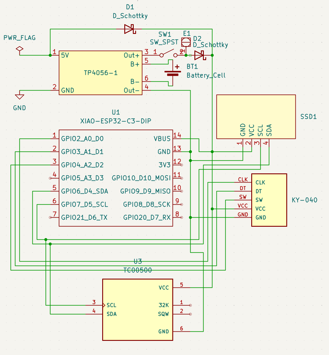
PCB Schematic

PCB schematic ^note that the part labeled E1 is because Kicad was mad I have the SS12F44 switch connected by wires instead of traces, please ignore

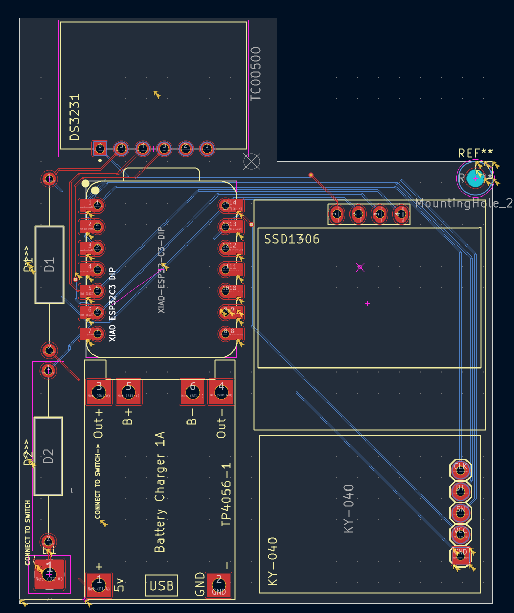
PCB Footprint

PCB footprint

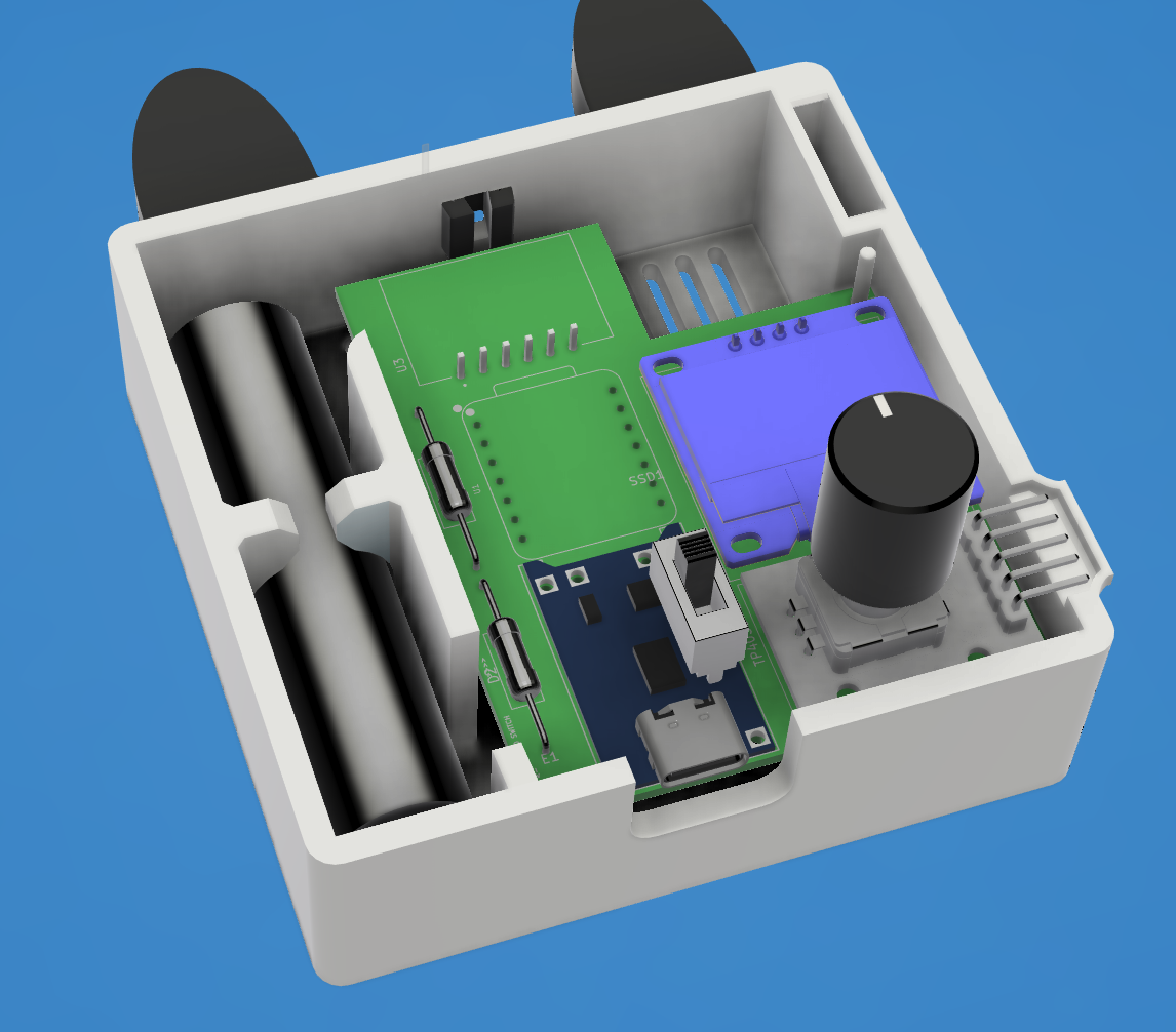
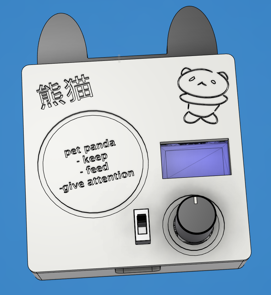
Case

Inside the 3D modeled case Outer 3D modeled case

assembly

steps:

  1. 3d print the case, case cover and panda ears
    • PLA is going to be used in this project but recommended to use a more stronger & less brittle filament for snap fits
  2. Flash the firmware by using Arduino IDE:
    1. Download the firmware folder and place the firmware folder inside a dedicated folder
    2. Unzip the libraries.zip and place "libraries" folder in the dedicated folder (named exactly that)
    3. Go to Arduino IDE File > Preferences and set the library folder to libraries
    4. Connect the XIAO ESP32C3 DIP to the computer with a USB-C cable, select the port that pops up and set the board as a "XIAO_ESP32C3"
    5. Go to "tomodachi_sketch.ino" and compile and upload
  3. Solder the components to the PCB
    • Use header pins to connect the throughholes on both the pcb and components for easier soldering (though tinning the holes will work too)
    • Make sure to insert the coin battery into the RTC after soldering (heat damage might hurt the battery)
  4. Solder a wire from the bottom left corner pad marked "CONNECT TO SWITCH" (not the throughholes connected to the D2 schottky diode) to one end of the SS12F44 switch's three pins, and then solder a wire from the Out+ of the TP4056 component (also marked with "CONNECT TO SWITCH") to the middle pin on the SS12F44 switch's three pins
    • The SS12F44 connects the middle pin with one or the other of the three pins depending on where it is switched
    • Use a short length wire when soldering the two places, and wrap each connection in electrical tape to ensure no short circuits happen
    • For both of the mentioned throughholes on the PCB probably don't use header pins as it will be easier to solder a wire without them
  5. Place the battery in the case first, then solder the wire from the battery's + end to the TP4056's 5V hole, and the battery's - end to the TP4056's GND hole (both located on the edge of the PCB)
  6. Assemble case with cover and ears

Parts

9
QtyValueFootprintReferences
2D_SchottkyResistor_THT:R_Axial_DIN0309_L9.0mm_D3.2mm_P20.32mm_HorizontalD1, D2
1KY-040tomodachi:KY-040-PORTKY-040
1TC00500tomodachi:MODULE_TC00500DS3231
1XIAO-ESP32-C3-DIPtomodachi:XIAO-ESP32-C3-DIPXIAO ESP32C3 DIP
1~tomodachi:TP4056-18650TP4056-1
1~Connector_Wire:SolderWire-0.75sqmm_1x01_D1.25mm_OD3.5mmE1
1~tomodachi:SSD1306128x64OLEDSSD1306

The 8 most common of 9 parts.

Similar boards

  • 2 layers103 × 30.5 mmTS Back Endcap, the printed circuit board in 3D

    TS Back Endcap

    EEVengers/ThunderScope

    ThunderScope GitHub Repo

    9 parts1.3kMIT
  • 2 layers31.8 × 47.6 mmNGC 38 connector, the printed circuit board in 3D

    NGC 38 connector

    rusefi/rusefi

    rusefi - GPL internal combustion engine control unit

    9 parts1.2k
  • 2 layers24 × 27.3 mmExpansion Card Retrofit, the printed circuit board in 3D

    Expansion Card Retrofit

    FrameworkComputer/ExpansionCards

    Reference designs and documentation to create Expansion Cards for the Framework Laptop

    9 parts1.1kCC-BY-4.0
  • 2 layers15.6 × 17.3 mmSKR Mini TFT Thermistor Board, the printed circuit board in 3D

    SKR Mini TFT Thermistor Board

    VoronDesign/Voron-Hardware

    Cool Hardware designed by the Voron Design group

    9 parts1.1kGPL-3.0
  • 2 layers39.1 × 49.5 mmLearnoliver, the printed circuit board in 3D

    Learnoliver

    hackclub/OnBoard

    💡 Join 1,000 teenagers and make your first PCB with a $100 grant!

    9 parts915
  • 2 layers17.4 × 16.9 mmToolhead, the printed circuit board in 3D

    Toolhead

    tanaes/whopping_Voron_mods

    9 parts787GPL-3.0
  • 2 layers9.8 × 108 mmExpander, the printed circuit board in 3D

    Expander

    wntrblm/Castor_and_Pollux

    A Juno-inspired dual oscillator

    9 parts587
  • 2 layersKeyboard after, the printed circuit board in 3D

    Keyboard after

    adamws/kicad-kbplacer

    KiCad plugin for automatic keyboard's key placement and routing

    9 parts547GPL-3.0

Questions

How big is the Tomodachi PCB?

It measures 56 × 69.5 mm and has 2 copper layers, 1.6 mm thick.

What parts does the Tomodachi use?

9 parts. The full list of its parts is on this page, with links to each part's symbol and footprint where PCBKit's library has them.

Where can I download the Tomodachi KiCad files?

From the yotepanda/tomodachi repository on GitHub, at the commit this page was made from: the board is src/cad/kicad/tomodachi.kicad_pcb and its schematic src/cad/kicad/tomodachi.kicad_sch. PCBKit opens the board in the browser, with nothing to install.

Can I use the Tomodachi design in my own project?

Its repository states no licence, so its author keeps all rights: ask yotepanda before reusing the design.