

2 layers130 × 88 mm
PicoXpander - Traffic Lights
yonush/picoXpander
picoXPander - learning programming with various IO boards and sensors
39 parts3

 yonush/picoXpander3
picoXPander - learning programming with various IO boards and sensors
PicoXpander - Driver Board is an open-source printed circuit board by yonush, from the yonush/picoXpander repository on GitHub. It is a 2-layer board of 106.3 × 88 mm with 122 parts on 115 nets, routed with 1,495 tracks and 128 vias.
It is built around the 74LVC06AD and BAT721S. Its parts include 54 resistors, 52 diodes, 7 capacitors, 6 ICs and 1 connector. It belongs with the RP2040 boards of this library.
This repo is the design files and sample code for the picoXpander kit. It is kit that leverages the Raspberry pico boards (RP2040 & RP2350) as a controller along with various IO boards the connect up using a short ribbon cable. The goal of this kit was to use simple technology to make an interesting electronics kit for teaching at a very affordable price. The focus of the learning is on the programming and understanding logic. This reduces the reliance on the connection and wiring up of individual components which take more time to get right.
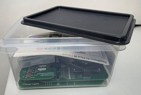
The Lunch box idea idea was create boards that are small enough to fit into a 1L box (about 160L x 113W x 90H mm in size. Like this one from Living & Co.), including the cable. This meant it was easy to keep the kit together and carry around. The 1L box has enough room to fit about 6-7 boards and the USB cable. An example of the lunch with three boards, cable and infomation card can be seen below.
The kit IO layout was arranged to match the picoPLC pinout so that you can write your applications using OpenPLC, CircuitPython, Micropython or C/C++, Python (with Blinka), TinyGo, Nim and Assemnby if you wish. Basically anything that can run on the Raspberyr Pico would work.
Pinout used by the picoXpander and picoPLC
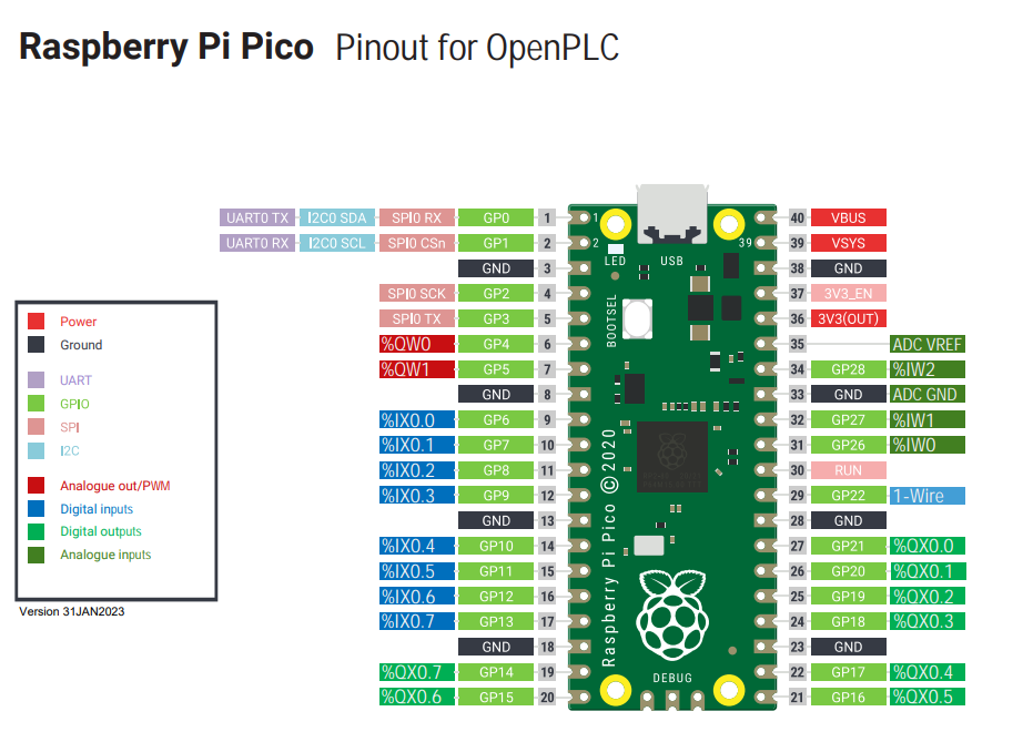
Support has been added to work with the Adafruit Blinka platform with some caveats. IN order to match the above pinout and work with the piocPLC there were several changes made to the Adafruit Blinka module. With a summary of the changes below. A more detailed writeup can be found in the readme for the picoXpander blinka distribution.
Changes made to adafruit_blinka module
The picoXpander driver board uses an off the shelf Raspberry Pico device which means there were no changes made to the USB HID (device VID) settings. We modified the existing rp2040_u2if driver, changes can be found in the blinka folder.
There are seven boards identified for the kit with three of them already designed and tested with the other four in progress
This board contains a socket for the Pico which also provision for direct soldering of the pico to the board. There is a room for a small I2C OLED display. (supports 0.91", 0.96", 1.3", 1.5" and 2.43" displays).
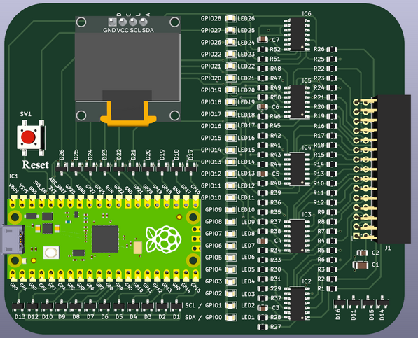
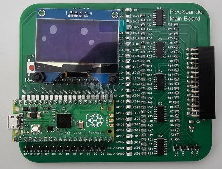
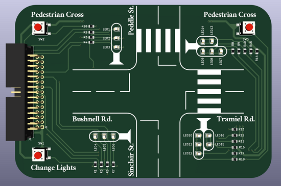
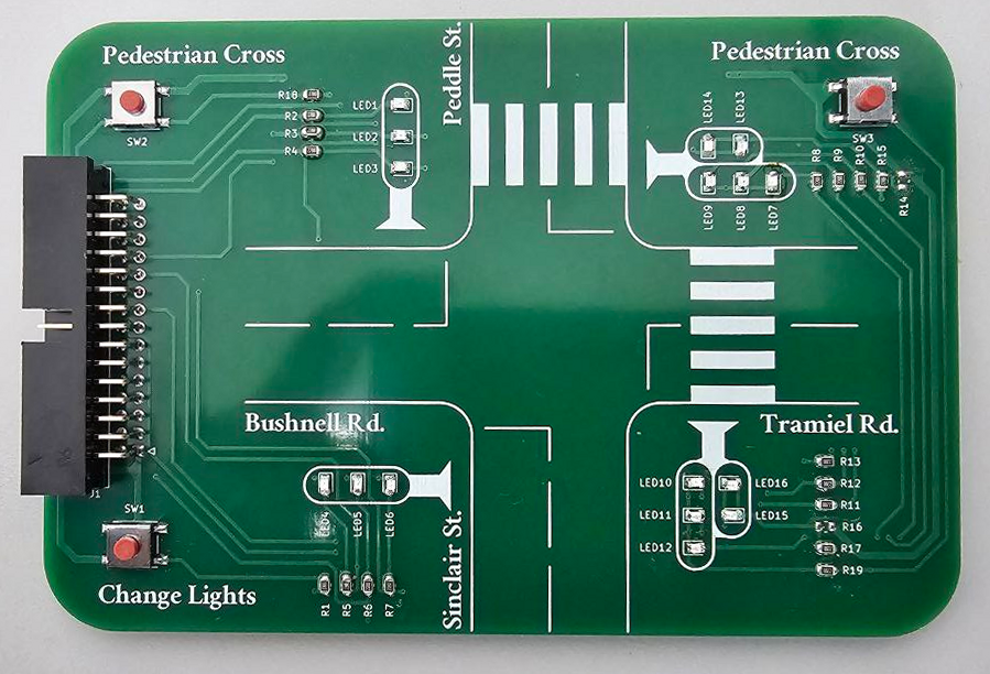
This simulates 4 way crossing with a pedestrian light for two of the roads.
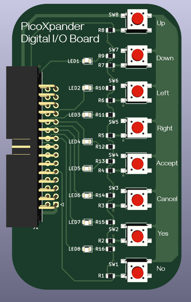
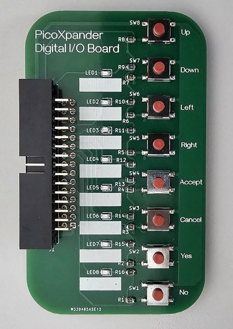
A simple board the maps against the 8 digital inputs and 8 digital outputs. The labels of the buttons are not tied to a specific function but can be used as identifiers.
A board to simulate a elevator with four floors.
Design currently under development.
Contains a 16x9 Charlieplexed LED matrix to present a very simple display driven by the rather convenient IS31FL3731 LED display chip.
Design currently under development.
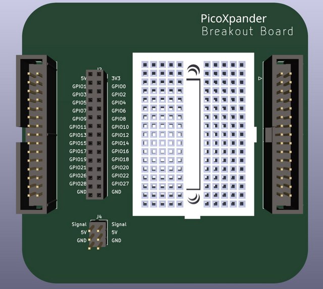
This board can either be attach to the driver board or between the driver board and another board. It provides the IO passthrough but also a header to allow you to attach dupont leads. A small breadboard is also attached to let you add components not found on the fixed function boards. A 6pin header has been added to provide connectivity for two small servos such as the MG90S and the SG90.
This board contains several common sensors and a a couple of RGB LEDs. Starting with the smart sensor BME688. It is an air quality sensor can measure gas, temperature, pressure and humiditthe first gas sensor with Artificial Intelligence
Sensor list
Design currently under development.
This board will have a motor driver for two motors to let you attach the pixoXpander to a chassi
Design currently under development.
Under development
-end-of-file-
| Qty | Value | Footprint | References |
|---|---|---|---|
| 26 | 220Ω | Resistor_SMD:R_0805_2012Metric | R29, R30, R31, R32, R33, R34, R35, R36, R37, R38, R39, R40, R41, R42, R43, R44 +10 |
| 26 | 22Ω | Resistor_SMD:R_0805_2012Metric | R1, R2, R11, R12, R13, R14, R15, R16, R17, R18, R19, R20, R21, R22, R23, R24 +10 |
| 26 | BAT721S | Package_TO_SOT_SMD:SOT-23 | D1, D2, D10, D11, D12, D13, D14, D15, D16, D17, D18, D19, D20, D21, D22, D23 +10 |
| 26 | Red | LED_SMD:LED_0805_2012Metric | LED1, LED2, LED10, LED11, LED12, LED13, LED14, LED15, LED16, LED17, LED18, LED19, LED20, LED21, LED22, LED23 +10 |
| 6 | 100n | Capacitor_SMD:C_0805_2012Metric | C2, C3, C4, C5, C6, C7 |
| 5 | 74LVC06 | Package_SO:SOIC-14_3.9x8.7mm_P1.27mm | IC2, IC3, IC4, IC5, IC6 |
| 2 | 4K7 | Resistor_SMD:R_0805_2012Metric | R9, R10 |
| 1 | 10µF | Capacitor_SMD:C_0805_2012Metric_Pad1.18x1.45mm_HandSolder | C1 |
| 1 | Display Module OLED I2C | Connector_PinHeader_2.54mm:PinHeader_1x04_P2.54mm_Vertical | M1 |
| 1 | IDC Header | Connector_PinSocket_2.54mm:PinSocket_2x15_P2.54mm_Horizontal | J1 |
| 1 | Pico | Custom_SBC:RPi_Pico_SMD_TH | IC1 |
| 1 | Reset | Button_Switch_SMD:SW_Push_1P1T_NO_6x6mm_H9.5mm | SW1 |
yonush/picoXpander
picoXPander - learning programming with various IO boards and sensors

yonush/picoXpander
picoXPander - learning programming with various IO boards and sensors

thomasdob/tdstatv3
A USB-controlled potentiostat/galvanostat for thin-film battery characterization


robfinch/Cores
Cores ===== RTF's Cores Use at your own risk. Welcome to my galaxy of cores. Contained in the directories are IP cores, source code for digital circuits.


fachat/csa_ultracpu
The CPU board for a 17MHz Colour-PET clone with modern interfaces


It measures 106.3 × 88 mm and has 2 copper layers, 1.6 mm thick.
122 parts, built around the 74LVC06AD and BAT721S. The full list of its parts is on this page, with links to each part's symbol and footprint where PCBKit's library has them.
From the yonush/picoXpander repository on GitHub, at the commit this page was made from: the board is hardware_designs/PCB/Driver/PicoXpander - Driver Board.kicad_pcb and its schematic hardware_designs/PCB/8bitIO/PicoXpander - IO Board.kicad_sch. PCBKit opens the board in the browser, with nothing to install.
Its repository states no licence, so its author keeps all rights: ask yonush before reusing the design.