2 layers57 × 55.2 mm
LogicAnalyzer
gusmanb/logicanalyzer
24 channel, 100Msps logic analyzer hardware and software
10 parts5.1kGPL-3.0

 yonathan-star/signal-lost
Signal Lost: an interactive PCB radio that tunes into fictional transmissions
Signal lost is an open-source printed circuit board by yonathan-star, from the yonathan-star/signal-lost repository on GitHub. It is a 2-layer board of 80 × 55 mm with 10 parts on 13 nets, routed with 74 tracks and 4 vias.
Its parts include 2 resistors, 2 diodes, 1 IC, 1 connector and 1 switch. It belongs with the radio and wireless boards and the ESP32 boards of this library.
An interactive PCB radio for fictional transmissions. Turn a dial to explore strange stations, watch the signal indicators, and find a hidden touch pad that unlocks a secret channel.
The goal is a small, tactile storytelling device that feels like recovered radio equipment: the interaction comes from tuning, light, sound, and clues printed on the board. The displayed frequencies and sounds are fictional; the device does not receive broadcast radio.
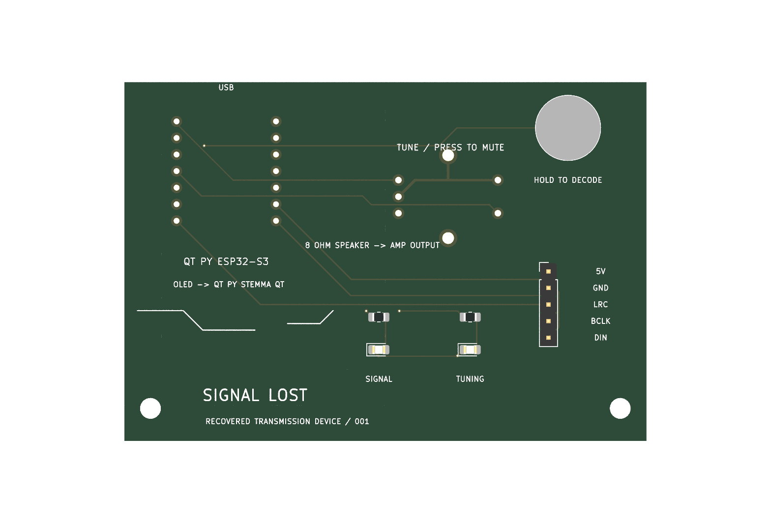
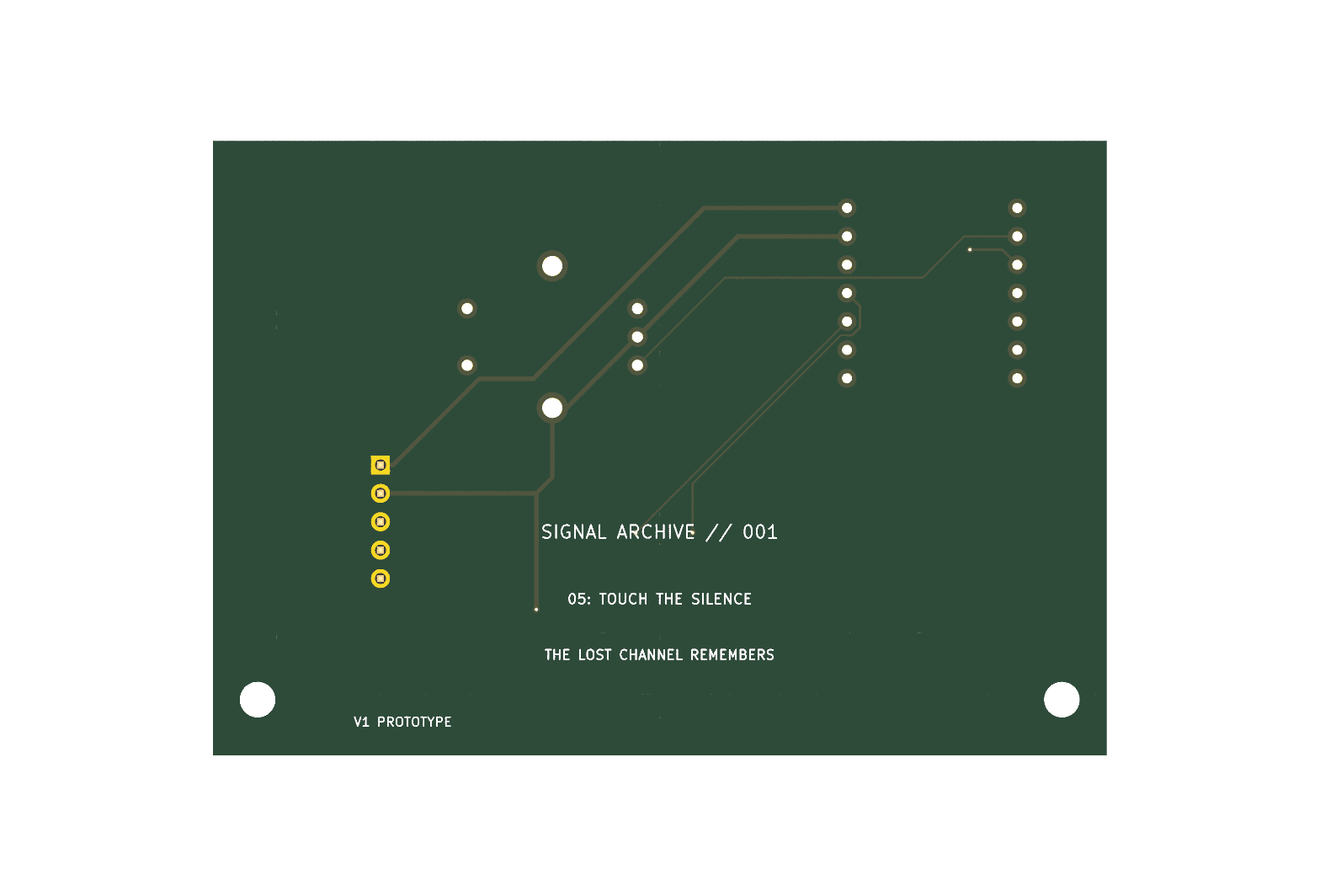
An Adafruit QT Py ESP32-S3 sits on a custom 80 × 55 mm, two-layer carrier PCB. A rotary encoder selects four ordinary stations: Night Weather, Distress, Numbers, and Deep Space. Pressing the dial toggles audio playback. The exposed copper touch pad selects the hidden Unknown station, and two LEDs show tuning and signal activity.
The firmware synthesizes tones, pulses, drones, and static at 16 kHz. A five-signal header carries power and I2S audio to an external MAX98357A amplifier; an 8 Ω, 1 W speaker connects to the amplifier output. An external 128 × 32 OLED uses the QT Py's STEMMA QT socket to display the station name and fictional frequency.
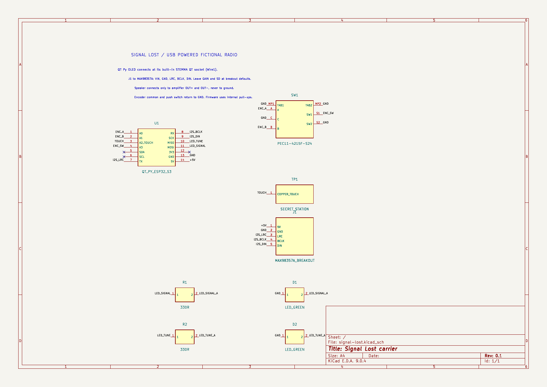
Open the schematic PDF · View the editable PCB on KiCanvas
PCB/signal-lost.kicad_pro in KiCad 9. The schematic, board, custom symbol library, footprint library, and library tables live together in PCB/. Keep that folder intact so ${KIPRJMOD} resolves the local libraries.firmware/ in PlatformIO. From that folder, run pio run -e qtpy_esp32s3 to build for the QT Py ESP32-S3 4 MB flash / 2 MB PSRAM variant. Dependencies are listed in platformio.ini.docs/DESIGN_NOTES.md. Use individual jumper leads for the amplifier because its breakout pins are not in carrier-header order. Connect the speaker only across amplifier OUT+ and OUT−. Start with low volume.fabrication/signal-lost-gerbers.zip. Check the purchased encoder pin pattern against the custom footprint before ordering.| Folder or file | Contents |
|---|---|
PCB/ | Editable KiCad project, schematic, PCB, custom symbols/footprints, and local library tables |
firmware/ | Arduino/PlatformIO source and build configuration |
fabrication/ | Gerbers, drill files, fabrication ZIP, and complete design-package ZIP |
images/ | PCB renders and schematic images |
docs/ | Assembly/design notes, schematic PDF, and existing ERC/DRC reports |
bom-signal-lost.csv | Component and PCB-fabrication list in CSV format |
BOM.md | Parts/funding record mirrored from Half Life |
JOURNAL.md, journal-evidence/ | Design journal and its supporting images |
The amounts below reproduce the recorded submission BOM; they are not fresh checkout quotes. Open the buying links to confirm current price, stock, shipping, and taxes.
| Part / material | Qty | Unit USD | Total USD | Buying link |
|---|---|---|---|---|
| Adafruit QT Py ESP32-S3 4MB/2MB PSRAM #5700 | 1 | $12.50 | $12.50 | DigiKey |
| Adafruit MAX98357A I2S amp breakout #3006 | 1 | $5.95 | $5.95 | DigiKey |
| Adafruit 0.91 inch 128x32 STEMMA QT OLED #4440 | 1 | $12.50 | $12.50 | DigiKey |
| Adafruit/Bourns rotary encoder with push switch and knob #377 | 1 | $4.50 | $4.50 | DigiKey |
| Same Sky CMS-30204-18L250 8 ohm 1 watt speaker | 1 | $2.74 | $2.74 | DigiKey |
| Adafruit STEMMA QT/Qwiic 50mm cable #4399 | 1 | $0.95 | $0.95 | DigiKey |
| Adafruit male break-away header pack #392 | 1 | $4.95 | $4.95 | DigiKey |
| Adafruit female-female 6-inch jumper wire pack #1950 | 1 | $1.95 | $1.95 | DigiKey |
| Yageo RC0805FR-10330RL 330 ohm 0805 resistor | 2 | $0.10 | $0.20 | DigiKey |
| Lite-On LTST-C170GKT green 0805 LED | 2 | $0.17 | $0.34 | DigiKey |
| 5-board batch: 80 x 55 mm 2-layer FR-4 lead-free HASL | 1 | $5.20 | $5.20 | JLCPCB |
Recorded parts and PCB subtotal: $51.78. The submission's tax/shipping estimate is $16.01, for an estimated $67.79 total. Tier 2 funding is $65, leaving a recorded $2.79 difference. A USB cable and future enclosure are not included in that subtotal. The source CSV and mirrored BOM retain the detailed notes.
The existing verification reports record zero schematic ERC errors or warnings, zero PCB DRC errors, and zero unconnected pads, with one front-silkscreen warning at the exposed touch pad. The firmware was previously compiled for the configured QT Py target. See docs/verification/.
This is a Design Week submission. The hardware has not been assembled or physically tested. The current design includes the carrier PCB and external modules; the enclosure, display/speaker mounts, and illuminated cutouts remain future work. First-build checks include touch calibration, encoder direction, OLED address, audio level, connector clearance, and the exact purchased encoder footprint.
| Qty | Value | Footprint | References |
|---|---|---|---|
| 2 | 330R | R_0805_2012Metric_Pad1.20x1.40mm_HandSolder | R1, R2 |
| 2 | LED_GREEN | LED_0805_2012Metric_Pad1.15x1.40mm_HandSolder | D1, D2 |
| 2 | M3 | MountingHole_3.2mm_M3 | H1, H2 |
| 1 | MAX98357A_BREAKOUT | PinHeader_1x05_P2.54mm_Vertical | J1 |
| 1 | PEC11-4215F-S24 | SignalLost:PEC11_Switch | SW1 |
| 1 | QT_PY_ESP32_S3 | SignalLost:QT_Py_ESP32_S3 | U1 |
| 1 | SECRET_STATION | SignalLost:Touch_Pad | TP1 |
gusmanb/logicanalyzer
24 channel, 100Msps logic analyzer hardware and software

byrantech/laptop
anyon_e, a highly integrated, high end, open source laptop. Attempt the impossible.

joeycastillo/Sensor-Watch
A board replacement for the classic Casio F-91W wristwatch


OLIMEX/OLINUXINO
OLINUXINO is Open Source / Open Hardware, low cost from EUR 24 Linux Industrial grade Single Board Computer capable to operate -25+85C

rusefi/rusefi
rusefi - GPL internal combustion engine control unit

VoronDesign/Voron-Hardware
Cool Hardware designed by the Voron Design group

hoglet67/RGBtoHDMI
Bare-metal Raspberry Pi project that provides pixel-perfect sampling of Retro Computer RGB/YUV video and conversion to HDMI
It measures 80 × 55 mm and has 2 copper layers, 1.6 mm thick.
10 parts. The full list of its parts is on this page, with links to each part's symbol and footprint where PCBKit's library has them.
From the yonathan-star/signal-lost repository on GitHub, at the commit this page was made from: the board is PCB/signal-lost.kicad_pcb and its schematic PCB/signal-lost.kicad_sch. PCBKit opens the board in the browser, with nothing to install.
Its repository states no licence, so its author keeps all rights: ask yonathan-star before reusing the design.