

2 layers82.8 × 25.1 mm
Pigmy CoryDora
balub/Pigmy-CoryDora
A compact 3-key macropad built around the Glyph Mini RP2040
15 parts5

 yawn156/flatboxP16
Low profile hitbox-layout fightstick
Flatbox rev5 is an open-source printed circuit board by yawn156, from the yawn156/flatboxP repository on GitHub. It is a 2-layer board of 210 × 120 mm with 40 parts on 35 nets, routed with 259 tracks and 31 vias.
It is built around the WS2812B and RP2040-ZERO. It belongs with the RP2040 boards of this library.
This fork is now using WS2812B-V5 from JLC, which include capacitors inside the circuit and also operate on 3.3v logic from the RP2040. Switch footprint supports Kaihl choc v1 and v2.
For the case I remixed Pettman's flatbox5 case to have a little window to show the active area of the screen. I'll only upload the remixed top case here, go to their repo for details and the bottom plate (I remixed the model that allows for threaded inserts so make sure to grab some M2x4 brass inserts.): https://github.com/pett-j/Flatbox-rev5-remix
If you want to use Choc V1 switches I recommend getting chocfox keycaps and using this button model: https://www.thingiverse.com/thing:6196955
For V2 switches you can use SGF's buttons: https://github.com/sgfdevices/Bridget/tree/main/Buttons
3D Printed Tact switch buttons: https://www.printables.com/model/470120-flatbox-tactile-switch-button
This repository contains a 3D-printable model and PCB design files to make an arcade controller that looks like this:
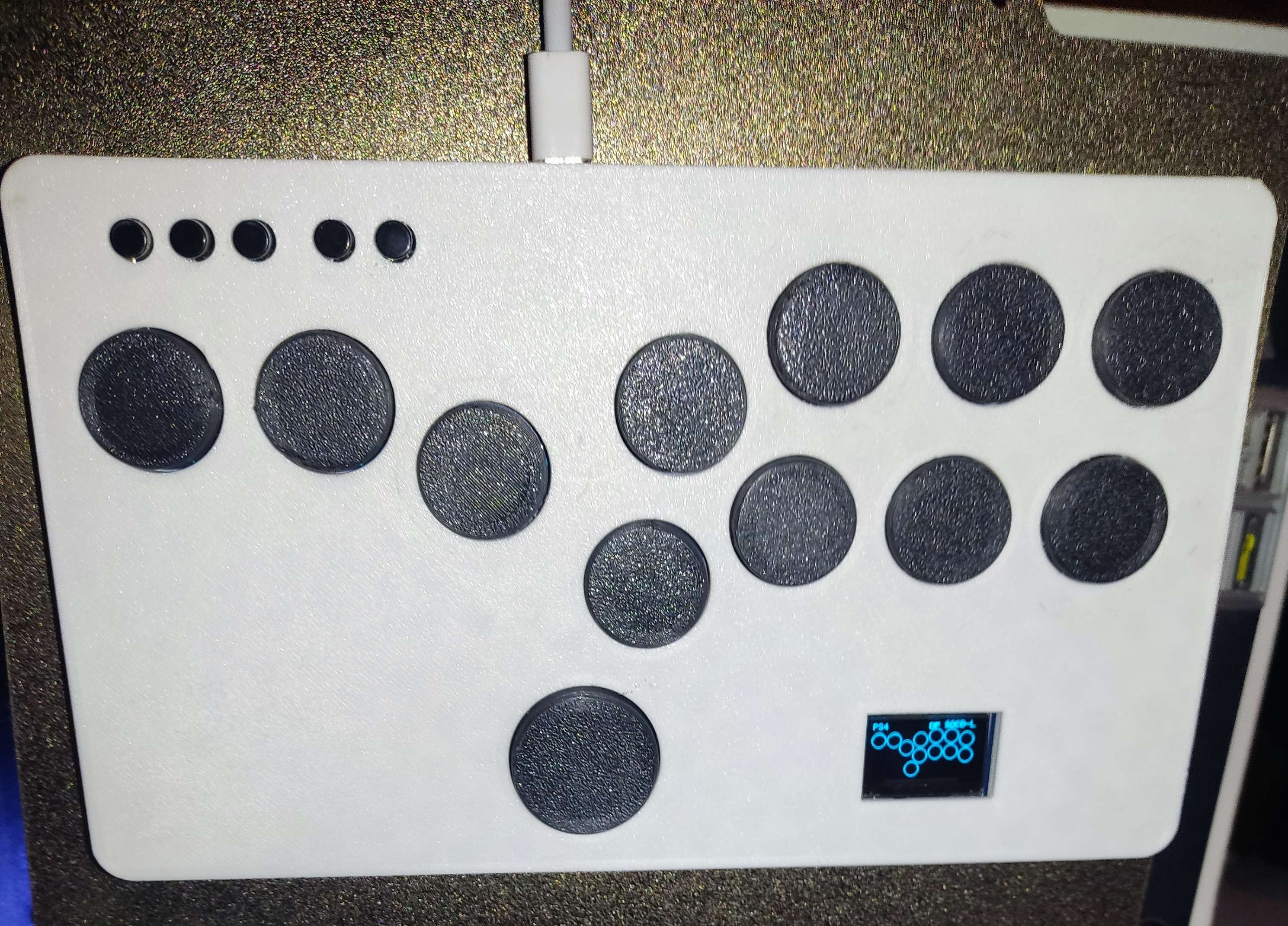
Note: Cheatbuttons are two extra buttons for easy thumb access, they have been added on the pcb but the case is still WIP.
MISC INFO: As I'm not keeping up with this project enough to have an updated build version with every release I'll note here the changes on the webconfigurator that you need to do in order for this to work, you can use the Flatbox rev5 or Flatbox rev5 RGB uf2 from the GP2040-CE repository.
-Display Configuration:
Use Display = Enabled
SDA Pin = 0
SCL Pin = 1
-RGB LED Configuration:
Data Pin = 29
LED layout = Hit Box Layout
Leds per button = 1
-Pin Mapping
S1 = 15
S2 = 14
L3 = 27
R3 = 28
A1 = 26
A2 = -1
| Qty | Value | Footprint | References |
|---|---|---|---|
| 14 | SW_Push | kaihl reversible:Kailh_socket_PG1350_reversible | cheatbutton01, cheatbutton02, SW7, SW8, SW9, SW10, SW11, SW12, SW13, SW14, SW15, SW16, SW17, SW18 |
| 12 | WS2812B | LED_SMD:LED_WS2812B_PLCC4_5.0x5.0mm_P3.2mm | D1, D2, D3, D4, D5, D6, D7, D8, D9, D10, D11, D12 |
| 7 | MountingHole | MountingHole:MountingHole_6.4mm_M6 | H1, H2, H3, H4, H5, H6, H7 |
| 5 | SW_Push | Button_Switch_THT:SW_PUSH_6mm_H5mm | HOME1, L3, R3, SELECT1, START1 |
| 1 | RP2040-Zero | RP2040-Zero:RP2040-Zero | A1 |
| 1 | SSD1306 | SSD1306:128x64OLED | OLED1 |
It measures 210 × 120 mm and has 2 copper layers, 1.6 mm thick.
40 parts, built around the WS2812B and RP2040-ZERO. The full list of its parts is on this page, with links to each part's symbol and footprint where PCBKit's library has them.
From the yawn156/flatboxP repository on GitHub, at the commit this page was made from: the board is hardware-rev 5 rgb oled/Extras/FlatboxP/Flatbox-rev5.kicad_pcb and its schematic hardware-rev 5 rgb oled/Extras/FlatboxP/Flatbox-rev5.kicad_sch. PCBKit opens the board in the browser, with nothing to install.
Its repository states no licence, so its author keeps all rights: ask yawn156 before reusing the design.
balub/Pigmy-CoryDora
A compact 3-key macropad built around the Glyph Mini RP2040


saujasrs/pygmy-corydora-pcbcupid
Pygmy Corydora Macropad Build at an event held by PCBCupid in Bangalore on May 18, 2026.