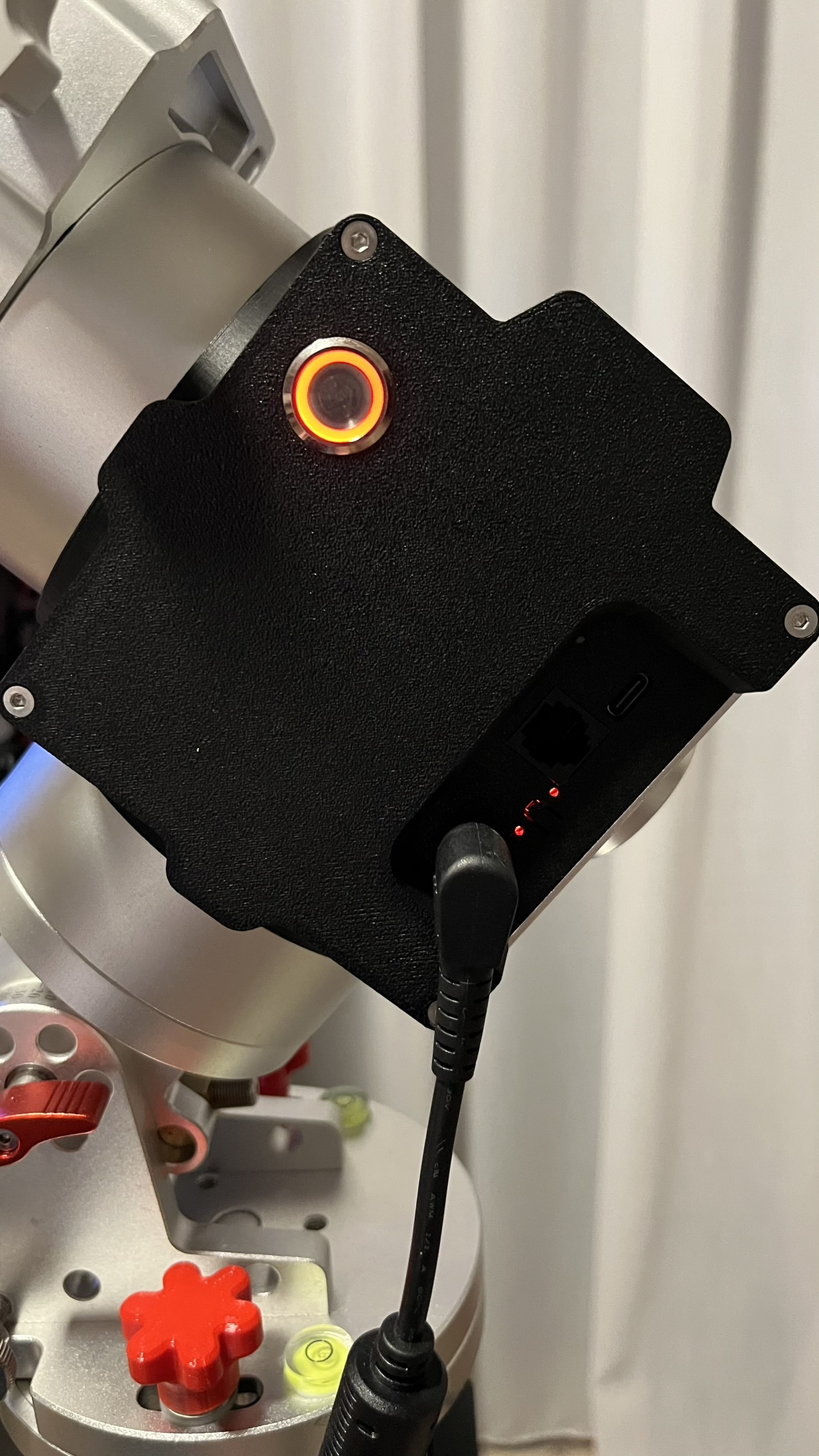
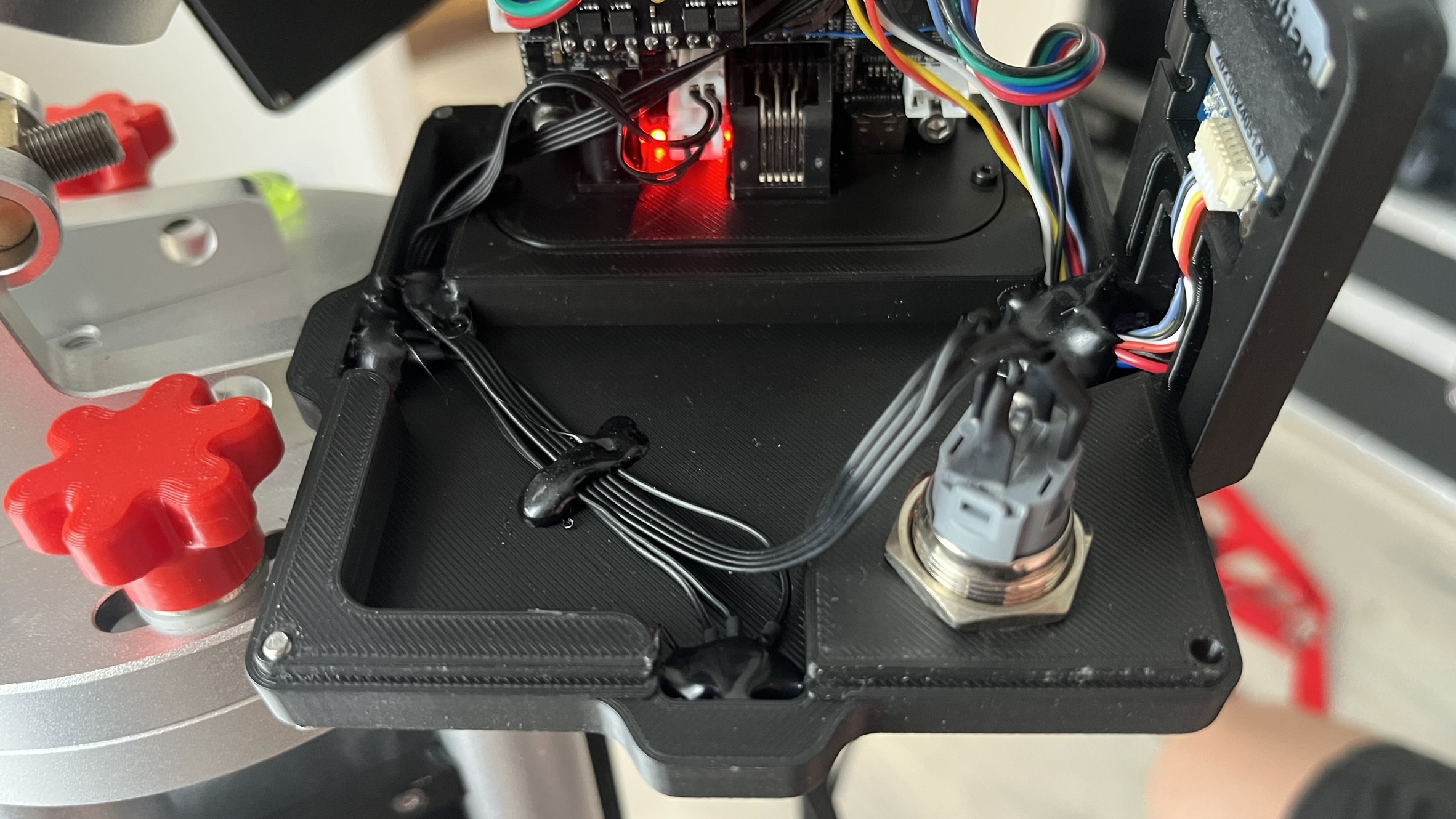
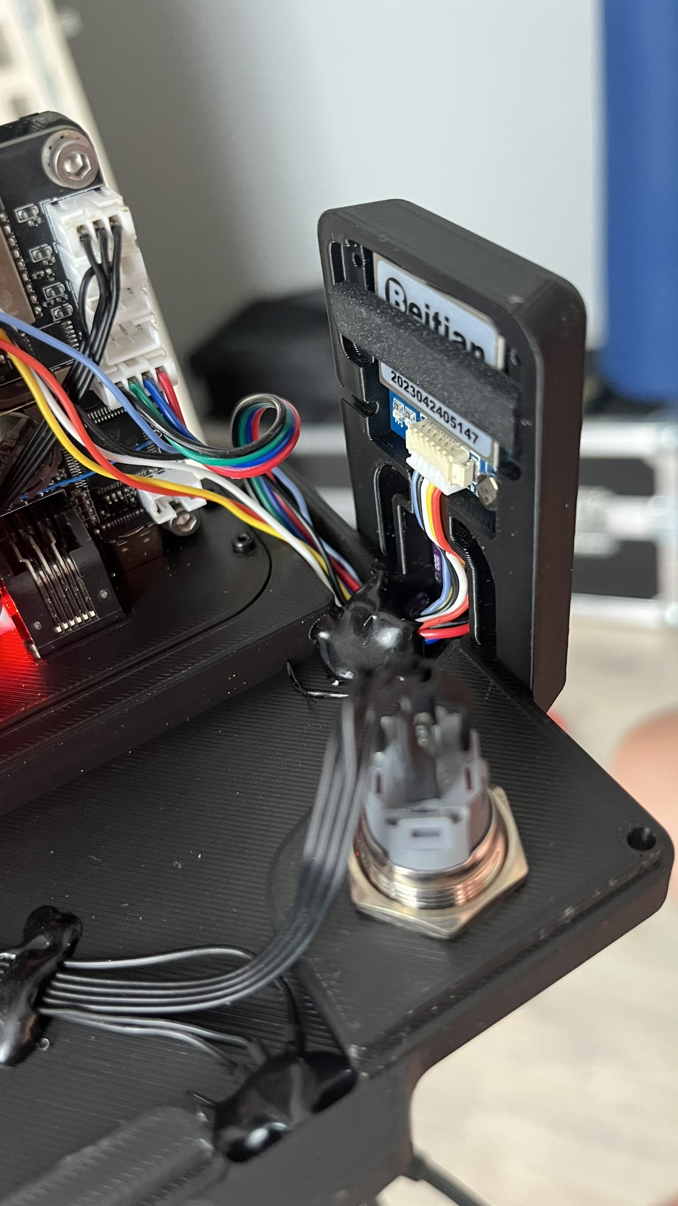
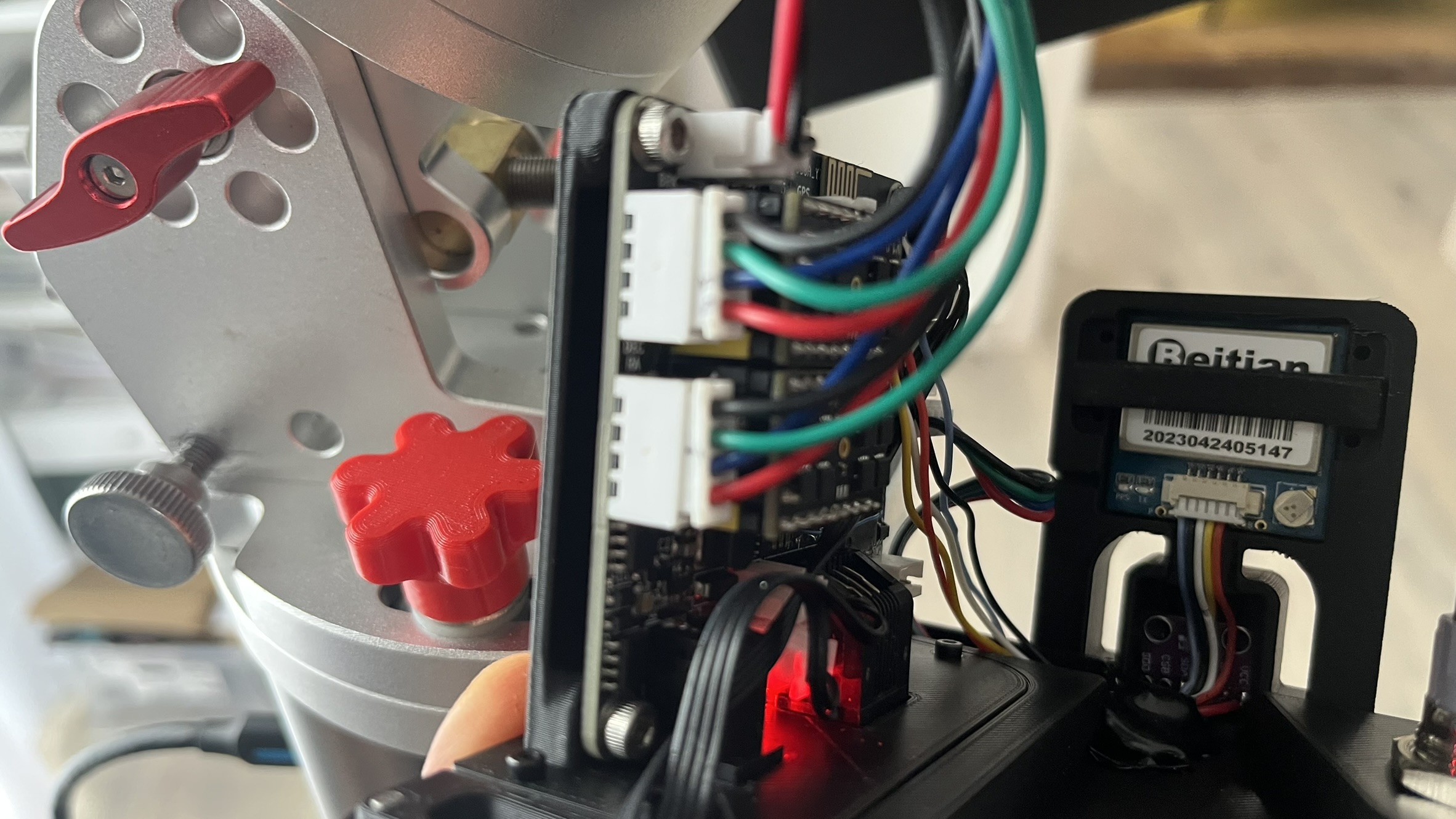
Juwei17onstep bck
Upgrade of Juwei17 Astronomy Mount
- Size
- 61 × 61 mm
- Copper layers
- 2
- Thickness
- 1.6 mm
- Parts
- 145
- Nets
- 155
- Pads
- 740
- Tracks, vias
- 1,100, 245
- Routed
- Yes
- KiCad
- KiCad 8.0 (file 20240108)
- Created
- 10 Aug 2025
- Updated
- 25 Sep 2025
Overview
Juwei17onstep bck is an open-source printed circuit board by xlazam01, from the xlazam01/Juwei17 repository on GitHub, published under the MIT licence. It is a 2-layer board of 61 × 61 mm with 145 parts on 155 nets, routed with 1,100 tracks and 245 vias.
It is built around the BME280, USBLC6-2SC6 and 24AA64T-I/OT, with the DS3231MZ+, 0603ESDA-05N and 100UF/35V among its other parts. Its parts include 48 capacitors, 40 resistors, 15 connectors, 12 ICs and 12 diodes. It belongs with the STM32 boards of this library.
Main components
12BME280
LGA-8(2.5x2.5)-40℃~+85℃ 0%RH~100%RH 1.71V~3.6V 1.8uA 16bit I2C、SPI ±0.5℃ ±3%RH LGA-8(2.5x2.5) Temperature and Humidity Sensor ROHSBoschTemperature And Humidity SensorUSBLC6-2SC6
SOT-23-60.35pF、0.8pF 100nA 150W@8/20us 15V 2 5V 6A@8/20us 6V ESD SOT-23-6 ESD and Surge Protection (TVS/ESD) ROHSUMWESD And Surge Protection (TVS/ESD)24AA64T-I/OT
SOT-23-5-40℃~+85℃ 1,000,000 cycles 1.7V~5.5V 200 Years 400kHz 5ms 64Kbit Hardware write protection function、Noise suppression function I2C SOT-23-5 EEPROM ROHSMicrochip TechnologyEEPROMDS3231MZ+
SOIC-8-40℃~+85℃ 2.3V~5.5V I2C Temperature compensation、Backup power management and battery charging、Alarm function、Periodic interrupt output SOIC-8 Real Time Clocks ROHSMaxim Integrated (Analog Devices)Real Time Clocks0603ESDA-05N
0603-55℃~+125℃ 1.5pF 100V 500nA 5V Bidirectional ESD IEC 61000-4-2 Single-channel 0603 ESD and Surge Protection (TVS/ESD) ROHSBORNESD And Surge Protection (TVS/ESD)100UF/35V
C1812C1812 SMT ROHSJLCPCB AssemblyUncategorisedAO4411
SOIC-81 P-Channel 1.12nF 122pF 18.4nC@10V 190pF 2.4V 24.5mΩ@10V 30V 3W 8A P-Channel SOIC-8 MOSFETs ROHSAlpha & Omega SemiconductorMOSFETsBZT52B12
SOD-123Zener DiodeshongjiachengDTC114E
--55℃~+150℃ 100mA 100nA 350mW 50V NPN - Bipolar (BJT)onsemiBipolar (BJT)FNR5040S100MT
SMD,5x5mm10uH 2.35A 2.7A 83mΩ Magnetic Shielded Inductor ±20% SMD,5x5mm Power Inductors ROHScjiangPower InductorsSMD0805P050TF
0805-40℃~+85℃ 1.5mm 100ms 100mΩ 1A 1mm 2.2mm 30A 500mA 500mW 6V 850mΩ 0805 Resettable Fuses ROHSRUILONResettable FusesSS34
SMA(DO-214AC)-55℃~+125℃ 3A 40V 500uA@40V 550mV@3A Independent SMA(DO-214AC) Schottky Diodes ROHSMDDSchottky Diodes
README
README.mdJuwei17 Mount Upgrade
🚀 Project Overview
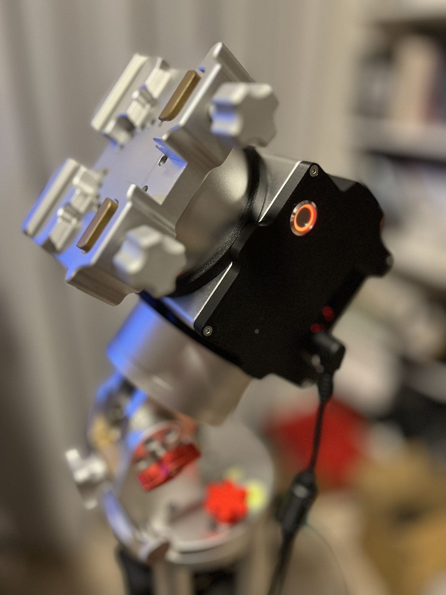
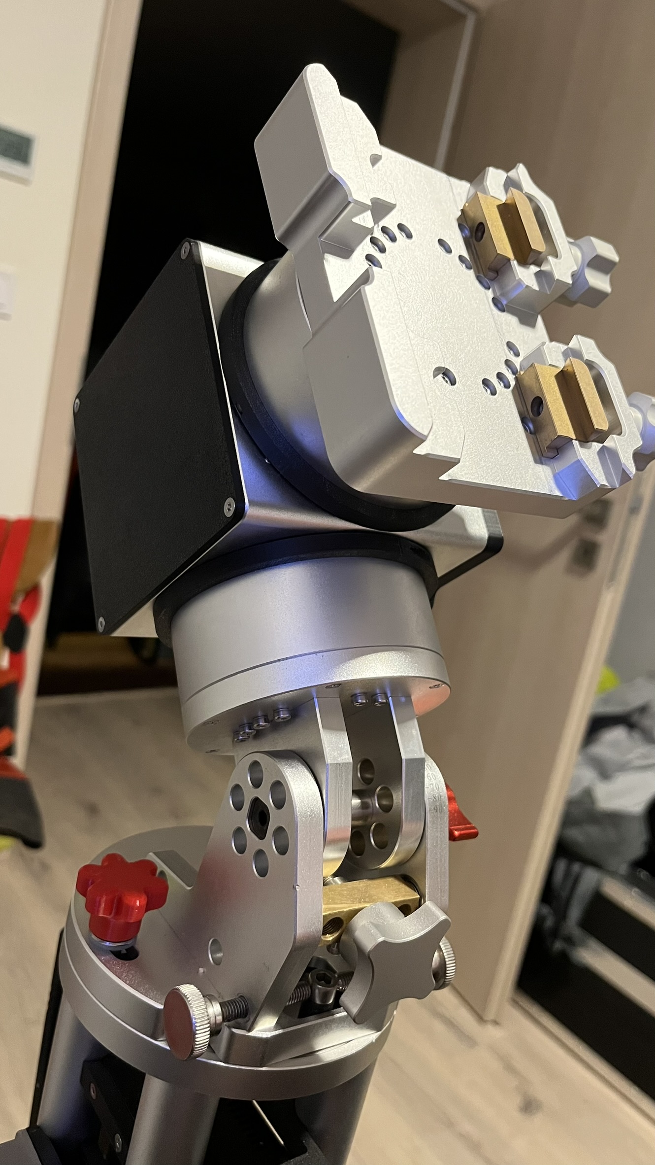
This repository contains subprojects to upgrade the Juwei17 mount with enhanced hardware, software, and mechanics. The goal is to provide a modern, feature-rich, and user-friendly experience for astronomy enthusiasts.
🧑🔧 Skills Needed
- Project is very DIY oriented
- PCB is very dense and it is recommended to manufacture it via some service (JLCPCB or similar)
- Some soldering (hall sensors, BME280, switch, connector crimping)
✨ Upgrade Features
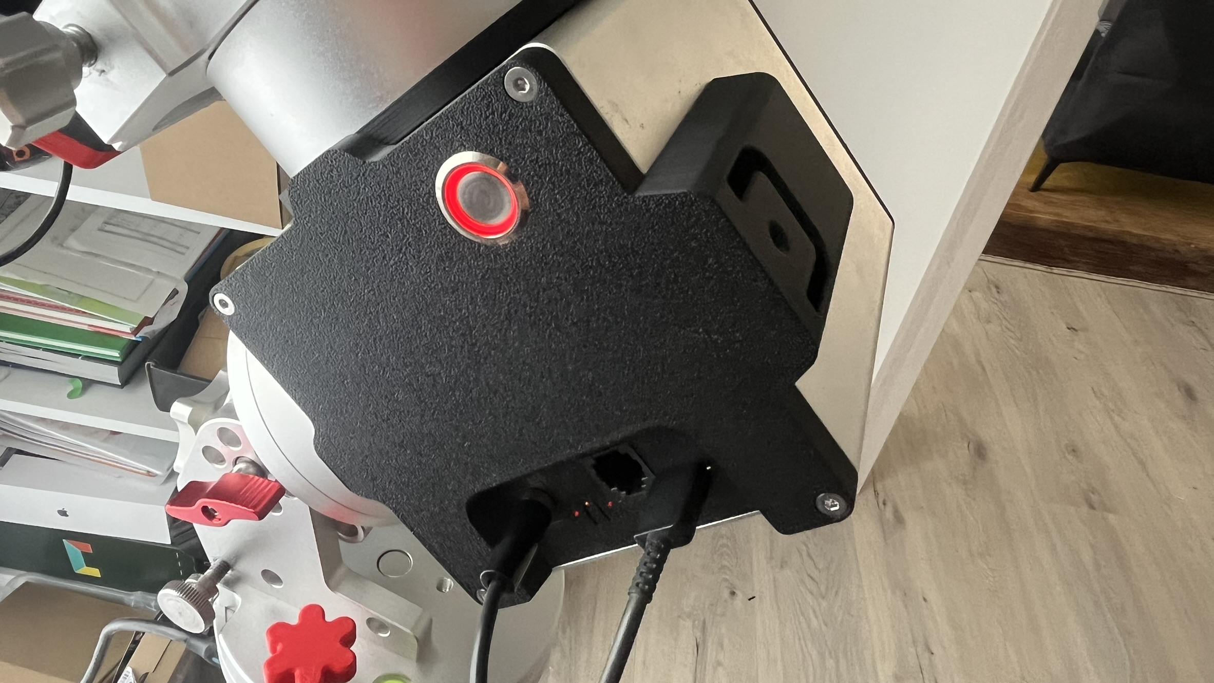
- Larger on/off switch
- Homing
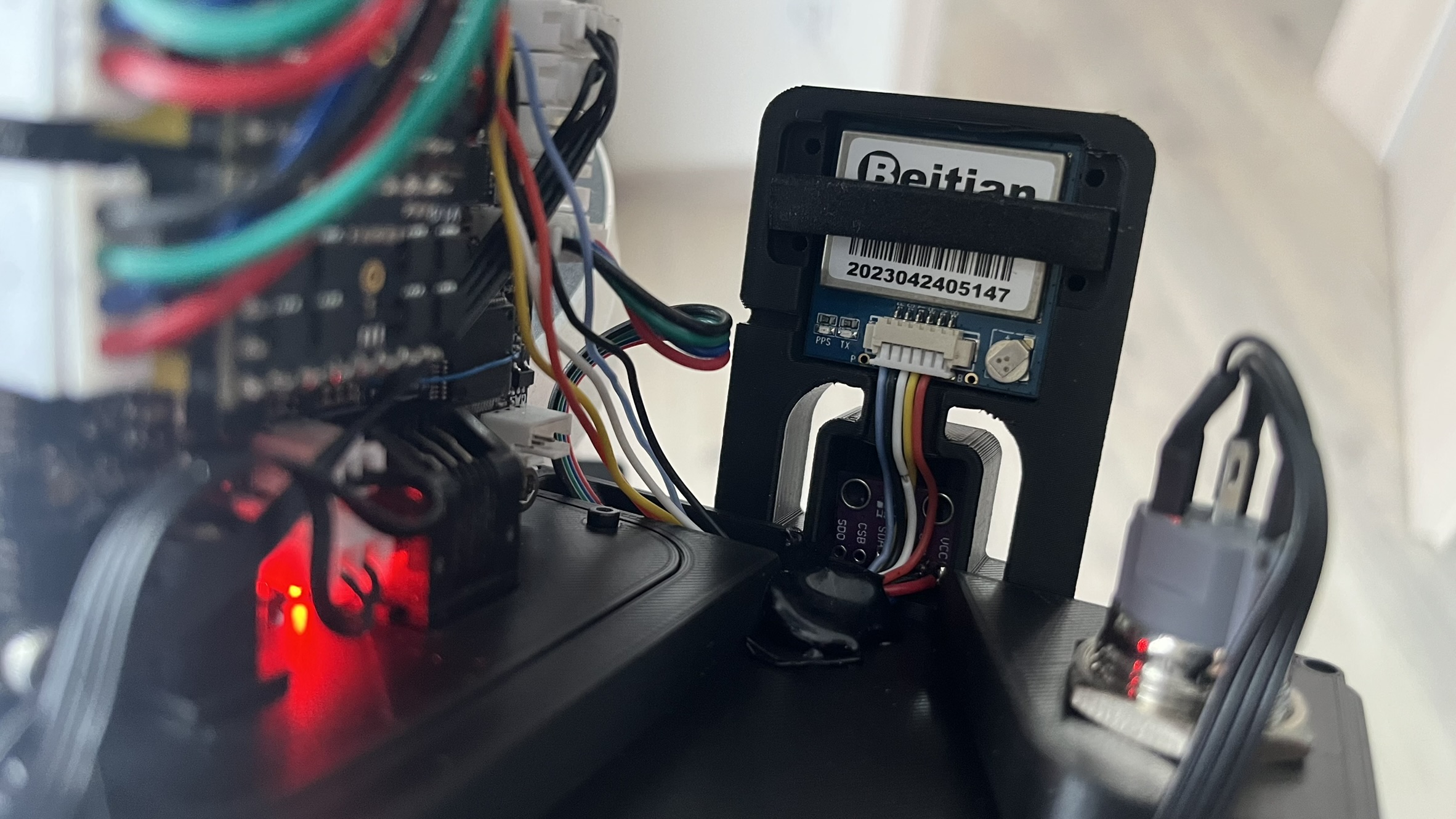
- GPS
- Weather sensors
- Fast slewing possible
- Support for TMC SPI or UART modules
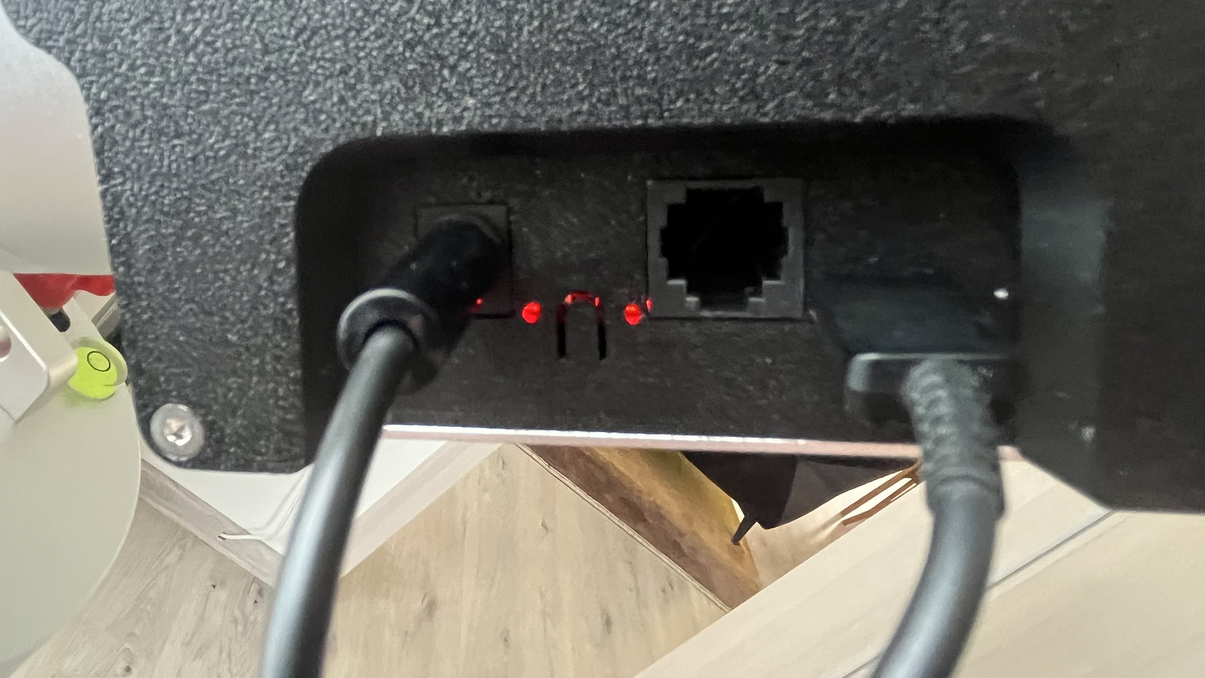
(TMC2209, TMC2130, TMC5160, etc.) - USB-C connector
- Programming button (no ST-Link needed)
- Loader application (semi-automatic programming for OnStep and SWS)
🧩 Hardware Features
- Minimized PCB size
- Support for Home and Limit switches
- OnWire interface
- GPS interface
- STM32F446 as main processor
- Power switch not needed:
- Mount will start without switch connected
- No high current goes through switch itself
- When switch is closed, mount is off
💾 Software Features
- Based on OnStepX (preconfigured, just upload)
- Added STM32 RTC support
- Modified Weather:
- Due to excessive BME self-heating
- Temperature from DS1820
- Humidity and pressure from BME280
- TLS fallback (STM32 → GPS)
- PlatformIO is used for OnStepX - My preferred IDE
- Arduino for SWS - due to specific version of ESP toolchain needed
🏗️ Mechanics
- CAD files
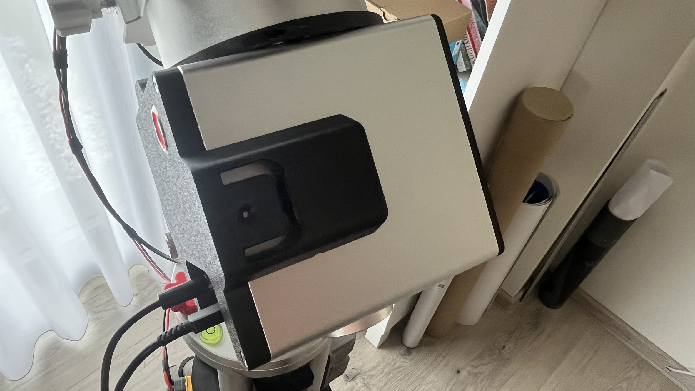
- STL files for 3D printing new covers
📦 Required Components
- New hardware - data on this github repo
- 2x TMC Drivers - you can reuse TMC2209 from your original main board
- Beitian BK-280 GPS module - link
- BME280 module - link
- DS1820 - link
- 2× 3144 hall sensors for homing functionality link
- 16mm antivandal switch - 16mm, 12-24V, latching - link
- Wires, connectors, hot glue, etc.
- Crimping pliers (Iwiss IWS-2820M)
- Magnetic rings:
- Magnets 20×5×2mm link ⚠️ Warning: Large deviation in sizes experienced!
- Screws M2×6 Voron style self-tapping screws - link
- 4x M3x16, 4x M3x10 countersunk
- optional 3144 hall sensor module for test link
- 5V power
- It can help you to check polarity and sensitivity for you DIY magnet rings
🛠️ Building Tips
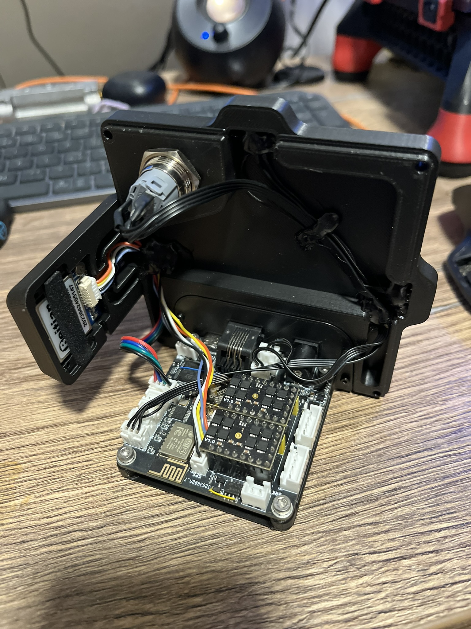
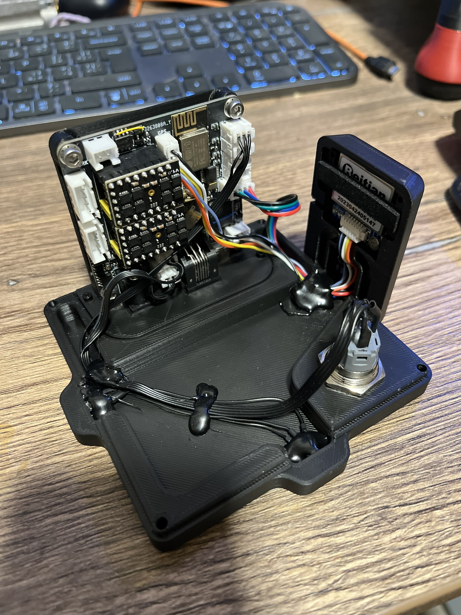
- Use hot glue to fix hall sensors and wires
- Mind the hall sensor "polarity" and magnets orientation in rings - good to check with dry run before mounting everything together
📁 Folder Description
- CAD: SolidEdge models (
*.parfiles) - HW: KiCad files (design and schematic PDF)
- Images: Build images
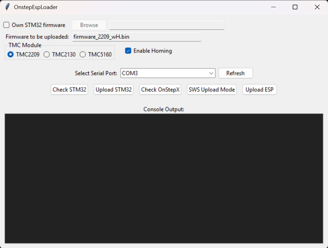
- OnstepEspLoader: Python app to support you through flashing process
- OnStepX: OnStep code (PlatformIO and VSCode)
- SmartWebServer: ESP8266 code (built in Arduino due to specific Espressif version)
- STLs: Files for 3D printing
📝 ToDo
- PEC
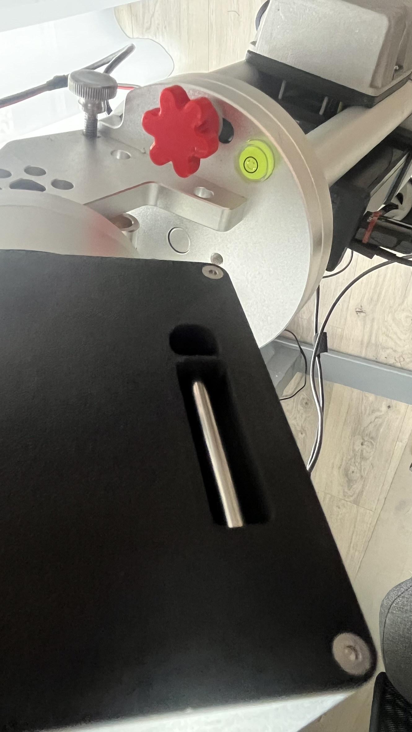
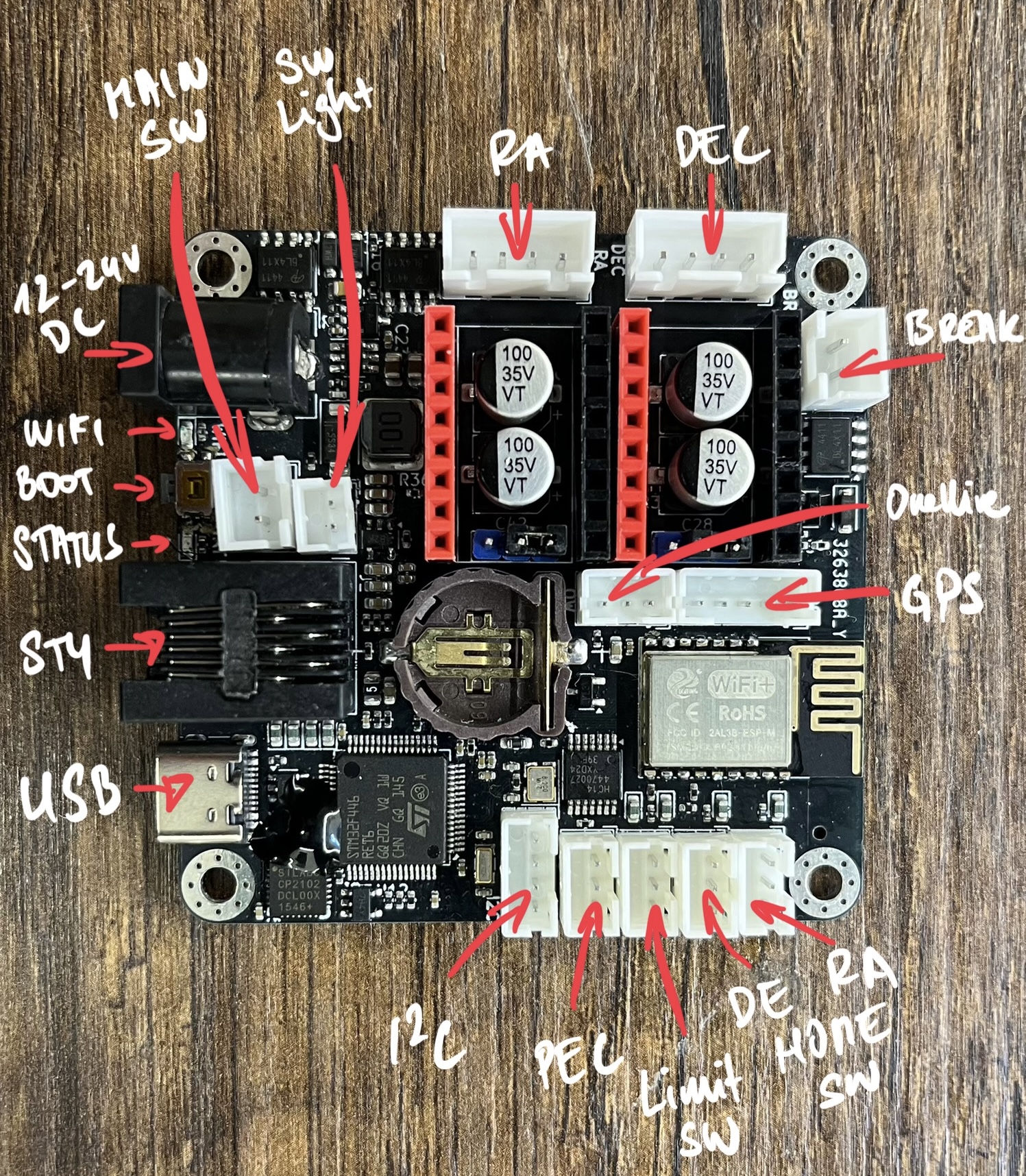
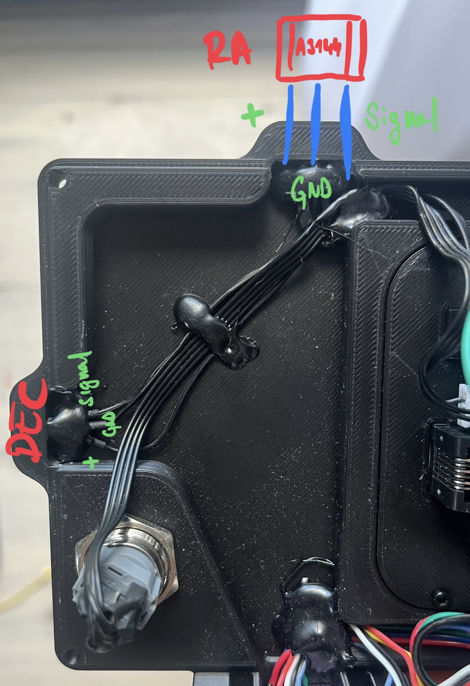
🖼️ Photo Gallery
🛠️ Assembly Instructions
- Print the required parts.
- Prepare magnets for the magnet rings:
- Ensure all magnets are oriented in the same direction.
- Take care to prevent magnets from snapping together unexpectedly.
- Test magnet polarity using a 3144 module or a bare sensor.
- Insert magnets into the rings.
- Fill roughly 90-180degrees
- Secure magnets with a thin layer of epoxy.
- 5min epoxy is ideal
- Assemble the front cover using small screws.
- Put together PCB_holder and front_panel
- Install hall sensors and wiring into the new cover.
- Insert hall sensor with right orientation (double check)
- Fix them in place with hotglue
- Mount the new 16mm switch and do wiring.
- We use NO contact for mount ON, NC contact for mount OFF
- Switch backlight is connected to mainboard
- Prepare and install wiring for the GPS and BME280 modules.
- Solder longer wires and cut them later to perfect length for BME280
- For GPS just cut the wire to perfect length
- Install modules in cavities
- Fix GPS with GPS_holder and small screws
- Install the DS1820 sensor in the second cover.
- Pressfit the sensor in place
- Cut wires to size
- Secure all wires with hot glue.
- Aim is to not have wires getting pinched during cover installation
- Trim wires to length and crimp connectors.
- Plug in jumper for UART/SPI TMC
- Insert TMC modules
- PCB installation
- Reuse brass standoff - insert them into holes in front cover
- Attach the PCB to these standoffs
- Connect all components together.
- Install back cover
- Plug in all connectors
- Install front cover
- Screw in four screws for the PCB from the bottom of the mount
- Assembly complete!
💻 Firmware Upload
- Power off the device.
- Press and hold the button next to the power connector.
- Power on the device.
- Observe the LEDs:
- OnStep status LED will be off.
- WiFi LED will blink if firmware is present; if the ESP is empty, both LEDs will be off.
- Start the OnstepEspLoader Python app.
- Select the correct TMC module type.
- Choose homing
- Click "Check STM32":
- The bootloader should respond.
- If it fails, click again.
- Click "Upload STM32":
- Firmware upload will start.
- Wait for the OnStep status LED:
- It should turn on after some time.
- The first boot may take longer as EEPROM is being formatted.
- Click "Check OnStep":
- It should respond with name and version.
- Switch to SWS mode:
- OnStep enters transparent mode and is ready to upload ESP firmware.
- Click "Upload ESP":
- Firmware for the webserver will be uploaded to the ESP.
- Finish:
- A soft reset will occur after some time, or you can power cycle the device manually.
⚙️ Default Firmware Configuration
Default firmware configuration expects:
- BME280, DS1820 - if initialization fails, there will be no weather information on webserver
- TMC2209, TMC5160 or TMC2130 - according to selected firmware during programming
- Correct polarity of HAL sensors for homing - if not fulfilled, homing will not work correctly
- Motor current is set to 1.0A for RUN and 1.3A for GOTO
- Homing sense is HIGH
🏗️ Build Your Own OnStepX
- If you use OnStepX from Howard Dutton - there will be no support for STM32 RTC (time and date will not be stored) and weather service will provide false temperatures from BME280 (self-heating)
- This could be potentially merged into main branch (I know that STM32 RTC was not planned - there are no official boards ready for this, weather fix is open)
- For my Juwei17 board use the OnStepX from this repository
- Change configuration as needed
- For upload use Serial Bootloader - depending on your IDE (Arduino, PlatformIO) how to do it
- There are three pads on the bottom of the PCB to connect to ST-Link - you need to solder wires or a connector with 2mm pitch
- If you want to use OnstepEspLoader just browse for your STM32 firmware binary
- Binary file pattern:
| Firmware Name | TMC Module | Homing |
|---|---|---|
| firmware_5160_wH | TMC5160 | With Homing |
| firmware_5160_woH | TMC5160 | Without Homing |
| firmware_2130_wH | TMC2130 | With Homing |
| firmware_2130_woH | TMC2130 | Without Homing |
| firmware_2209_wH | TMC2209 | With Homing |
| firmware_2209_woH | TMC2209 | Without Homing |
Parts
145| Qty | Value | Footprint | References |
|---|---|---|---|
| 9 | 100n/50V | Capacitor_SMD:C_0402_1005Metric | C26, C27, C28, C29, C35, C36, C37, C38, C41 |
| 7 | 0603ESDA-05N | Diode_SMD:D_0603_1608Metric | D3, D4, D5, D6, D8, D9, D10 |
| 7 | 10uF/10V | Capacitor_SMD:C_0603_1608Metric | C3, C11, C14, C15, C16, C22, C47 |
| 6 | 100k | Resistor_SMD:R_0402_1005Metric | R10, R11, R18, R22, R31, R37 |
| 6 | 100n | Capacitor_SMD:C_0402_1005Metric | C7, C8, C9, C10, C20, C21 |
| 6 | 10k | Resistor_SMD:R_0402_1005Metric | R6, R21, R25, R26, R27, R34 |
| 6 | 4.7u/25V | Capacitor_SMD:C_0805_2012Metric | C23, C24, C30, C32, C33, C39 |
| 5 | 100uF/35V | Capacitor_SMD:CP_Elec_6.3x7.7 | C12, C40, C42, C43, C44 |
| 4 | 0.11R/0805 | Resistor_SMD:R_0805_2012Metric | R19, R20, R23, R24 |
| 4 | 10k | Capacitor_SMD:C_0402_1005Metric | R2, R3, R4, R5 |
| 4 | 1k | Resistor_SMD:R_0402_1005Metric | R9, R38, R39, R40 |
| 4 | 4k7 | Resistor_SMD:R_0402_1005Metric | R16, R17, R30, R32 |
| 4 | 5k1 | Resistor_SMD:R_0402_1005Metric | R7, R8, R35, R36 |
| 4 | EVQPUM | Button_Switch_SMD:SW_Push_1P1T_NO_CK_KMR2 | ESP_BOOT1, ESP_RST1, RST1, RST2 |
| 4 | MountingHole | MountingHole:MountingHole_3.2mm_M3_Pad_Via | H1, H2, H3, H4 |
| 3 | 10u/25V | Capacitor_SMD:C_0805_2012Metric | C2, C18, C19 |
| 3 | 1k | Capacitor_SMD:C_0402_1005Metric | R28, R29, R33 |
| 3 | 22n/50V | Capacitor_SMD:C_0402_1005Metric | C25, C31, C34 |
| 2 | 100nF | Capacitor_SMD:C_0402_1005Metric | C45, C48 |
| 2 | 1uF/10V | Capacitor_SMD:C_0402_1005Metric | C5, C13 |
| 2 | 20pF | Capacitor_SMD:C_0402_1005Metric | C1, C4 |
| 2 | 22R | Resistor_SMD:R_0402_1005Metric | R12, R13 |
| 2 | AO4411 | Package_SO:SOIC-8_3.9x4.9mm_P1.27mm | Q1, Q2 |
| 2 | LED | LED_SMD:LED_0603_1608Metric | D1, D12 |
| 2 | RA_2.54mm | Connector_Molex:Molex_KK-254_AE-6410-04A_1x04_P2.54mm_Vertical | J13, J14 |
| 2 | RA_2mm | Connector_JST:JST_PH_B4B-PH-K_1x04_P2.00mm_Vertical | J11, J12 |
| 2 | USBLC6-2SC6 | Package_TO_SOT_SMD:SOT-23-6 | U5, U13 |
| 2 | USB_C_Receptacle_USB2.0 | Connector_USB:USB_C_Receptacle_G-Switch_GT-USB-7010ASV | J1, J10 |
| 2 | ~ | Package_DFN_QFN:QFN-28-1EP_5x5mm_P0.5mm_EP3.75x3.75mm_ThermalVias | U2, U3 |
| 1 | 100n/50V/0603 | Capacitor_SMD:C_0402_1005Metric | C17 |
| 1 | 1MEG | Capacitor_SMD:C_0402_1005Metric | R1 |
| 1 | 1uF | Capacitor_SMD:C_0402_1005Metric | C46 |
| 1 | 24AA64T-I/OT | Package_TO_SOT_SMD:SOT-23-5 | U9 |
| 1 | 2u2/6.3 | Capacitor_SMD:C_0402_1005Metric | C6 |
| 1 | 36k | Resistor_SMD:R_0402_1005Metric | R14 |
| 1 | 5.5/2.1 Barell DC3 | Connector_BarrelJack:BarrelJack_Wuerth_6941xx301002 | J3 |
| 1 | 6k8 | Resistor_SMD:R_0402_1005Metric | R15 |
| 1 | BLM18HE601SH1D | Inductor_SMD:L_0603_1608Metric_Pad1.05x0.95mm_HandSolder | L1 |
| 1 | BME280 | Package_LGA:Bosch_LGA-8_2.5x2.5mm_P0.65mm_ClockwisePinNumbering | U11 |
| 1 | BZT52B12 | Diode_SMD:D_SOD-123F | D7 |
| 1 | BZT52Bxx | Diode_SMD:D_SOD-123F | D11 |
| 1 | Battery_Cell | myLib_SMD:CR1220_holder | BT1 |
| 1 | CP2102N-Axx-xQFN28 | Package_DFN_QFN:QFN-28-1EP_5x5mm_P0.5mm_EP3.35x3.35mm | U12 |
| 1 | Conn_01x02 | Connector_Molex:Molex_KK-254_AE-6410-02A_1x02_P2.54mm_Vertical | J8 |
| 1 | DEC_HOME | Connector_JST:JST_PH_B3B-PH-K_1x03_P2.00mm_Vertical | J5 |
| 1 | DS3231M | Package_SO:SOIC-16W_7.5x10.3mm_P1.27mm | U4 |
| 1 | DTC114E | Package_TO_SOT_SMD:SOT-23 | Q3 |
| 1 | ESP_UART | Connector_JST:JST_PH_B3B-PH-K_1x03_P2.00mm_Vertical | J9 |
| 1 | FNR5040S100MT | myLib_SMD:L_5.5x5.1mm | L2 |
| 1 | GPS | Connector_JST:JST_PH_B4B-PH-K_1x04_P2.00mm_Vertical | J7 |
| 1 | I2C | Connector_JST:JST_PH_B4B-PH-K_1x04_P2.00mm_Vertical | J15 |
| 1 | LIMIT | Connector_JST:JST_PH_B3B-PH-K_1x03_P2.00mm_Vertical | J6 |
| 1 | ME3116 | myLib_SMD:SOT-23-6_Handsoldering | U8 |
| 1 | ME6211 | Package_TO_SOT_SMD:SOT-23-5 | U7 |
| 1 | RA_HOME | Connector_JST:JST_PH_B3B-PH-K_1x03_P2.00mm_Vertical | J4 |
| 1 | RJ12 | Connector_RJ:RJ12_Amphenol_54601-x06_Horizontal | J2 |
| 1 | SMD0805P050TF | Fuse:Fuse_0805_2012Metric | F1 |
| 1 | SS34 | Diode_SMD:D_SMA | D2 |
| 1 | STM32F411CCUx | Package_DFN_QFN:QFN-48-1EP_7x7mm_P0.5mm_EP5.6x5.6mm | U6 |
| 1 | SW_SPST | myLib_THT:MTS-102-C4 | SW2 |
| 1 | SW_Slide_DPDT | Button_Switch_THT:SW_CK_JS202011CQN_DPDT_Straight | SW1 |
| 1 | TAXM8M4RDBCCT2T / 8MHz 3225 | Crystal:Crystal_SMD_3225-4Pin_3.2x2.5mm | Y1 |
| 1 | ~ | myLib_SMD:ESP_M2 | U1 |
More from xlazam01/Juwei17
1- 2 layers61 × 61 mm

Similar boards
- 2 layers120.1 × 46 mm

- 4 layers70 × 50 mm

PD Smart Supply
JaphD/USB-C-PD-Smart-Power-Supply
A compact STM32-controlled USB-C Power Delivery supply providing selectable 5 V, 9 V, 12 V, and 20 V outputs up to 3 A.
73 parts - 2 layers71.1 × 120.9 mm

- 2 layers80 × 60 mm

Mecanum robot board
adammat02/mecanum_robot_board
A compact STM32-based controller board for a four-wheel mecanum robot. It drives four DC gear motors with quadrature-encoder feedback, reads two time-of-flight distance sensors, and breaks out the common serial buses -…
88 parts - 4 layers300 × 200 mm

- 4 layers100.8 × 21.8 mm

- 4 layers130 × 110 mm

- 2 layers35 × 42 mm

AstroUniBoard
xlazam01/AstroUniBoard
STM32G0B1-based telescope focuser/rotator controller — OnStepX firmware port + KiCad PCB
146 parts1GPL-3.0
Questions
How big is the Juwei17onstep bck PCB?
It measures 61 × 61 mm and has 2 copper layers, 1.6 mm thick.
What parts does the Juwei17onstep bck use?
145 parts, built around the BME280, USBLC6-2SC6, 24AA64T-I/OT and DS3231MZ+. The full list of its parts is on this page, with links to each part's symbol and footprint where PCBKit's library has them.
Where can I download the Juwei17onstep bck KiCad files?
From the xlazam01/Juwei17 repository on GitHub, at the commit this page was made from: the board is HW/v2.1/juwei17onstep_bck.kicad_pcb and its schematic HW/v2.1/ME3116.kicad_sch. PCBKit opens the board in the browser, with nothing to install.
Can I use the Juwei17onstep bck design in my own project?
Its repository publishes it under the MIT licence: you may reuse it on that licence's terms (keep the author's notice, and for a copyleft licence share your changes alike).