
2 layers57 × 55.2 mm
LogicAnalyzer
gusmanb/logicanalyzer
24 channel, 100Msps logic analyzer hardware and software
10 parts5.1kGPL-3.0

 wkcollis1-eng/mmwave-presence-node
HLK-LD2410C 24 GHz presence sensor on a XIAO ESP32-C3, driving room lighting via Home Assistant. Design doc, KiCad carrier PCB, ESPHome firmware.
MmWave Presence Lighting Node is an open-source printed circuit board by wkcollis1-eng, from the wkcollis1-eng/mmwave-presence-node repository on GitHub. It is a 2-layer board of 44 × 33 mm with 10 parts on 9 nets, routed with 50 tracks and 68 vias.
Its parts include 3 capacitors, 2 ICs and 1 resistor. It belongs with the lEDs and displays and home automation and IoT boards and the ESP32 and RISC-V boards of this library.
24 GHz Radar Presence Sensing for Room Lighting






A 24 GHz radar presence sensor that turns a room's lamps on when someone walks in and off some minutes after they leave — including for a person sitting still, in the dark, reading, whom a PIR sensor cannot see.
An HLK-LD2410C radar and an Adafruit VEML7700 light sensor on a Seeed XIAO ESP32-C3 carrier board, running ESPHome, with the control logic in Home Assistant.
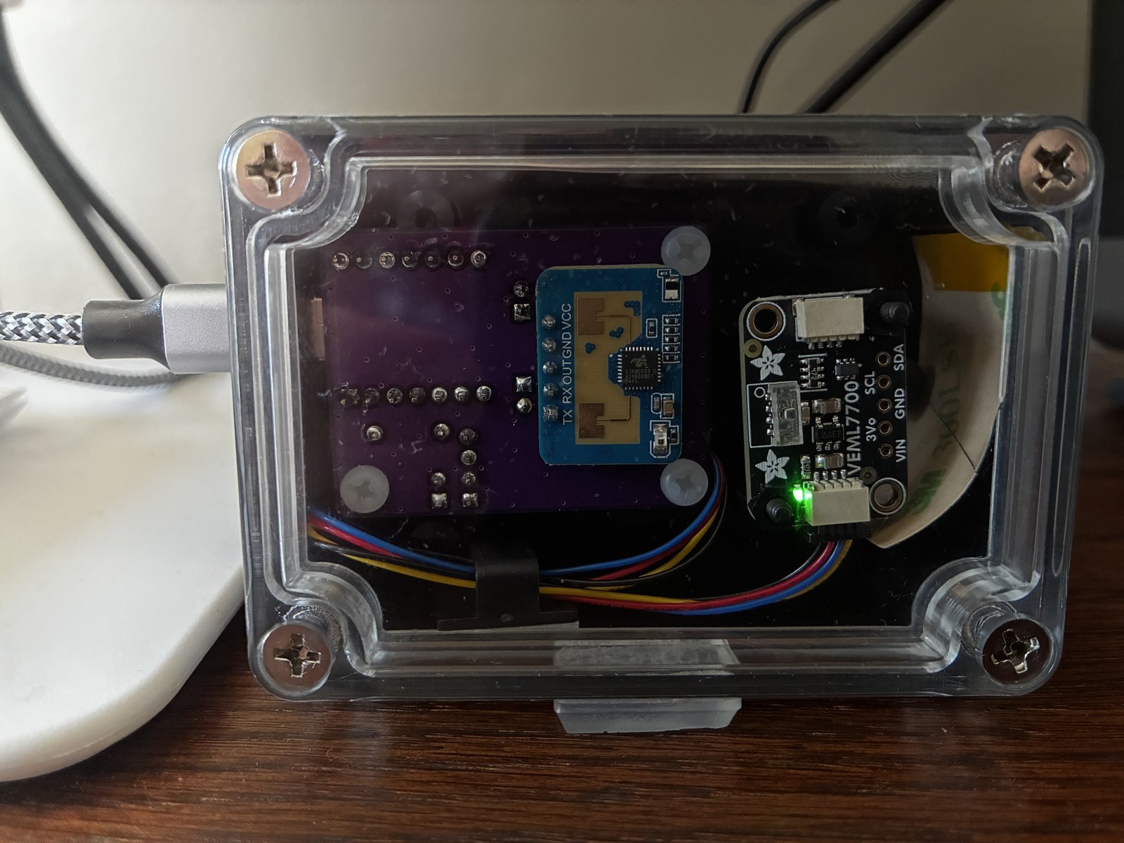
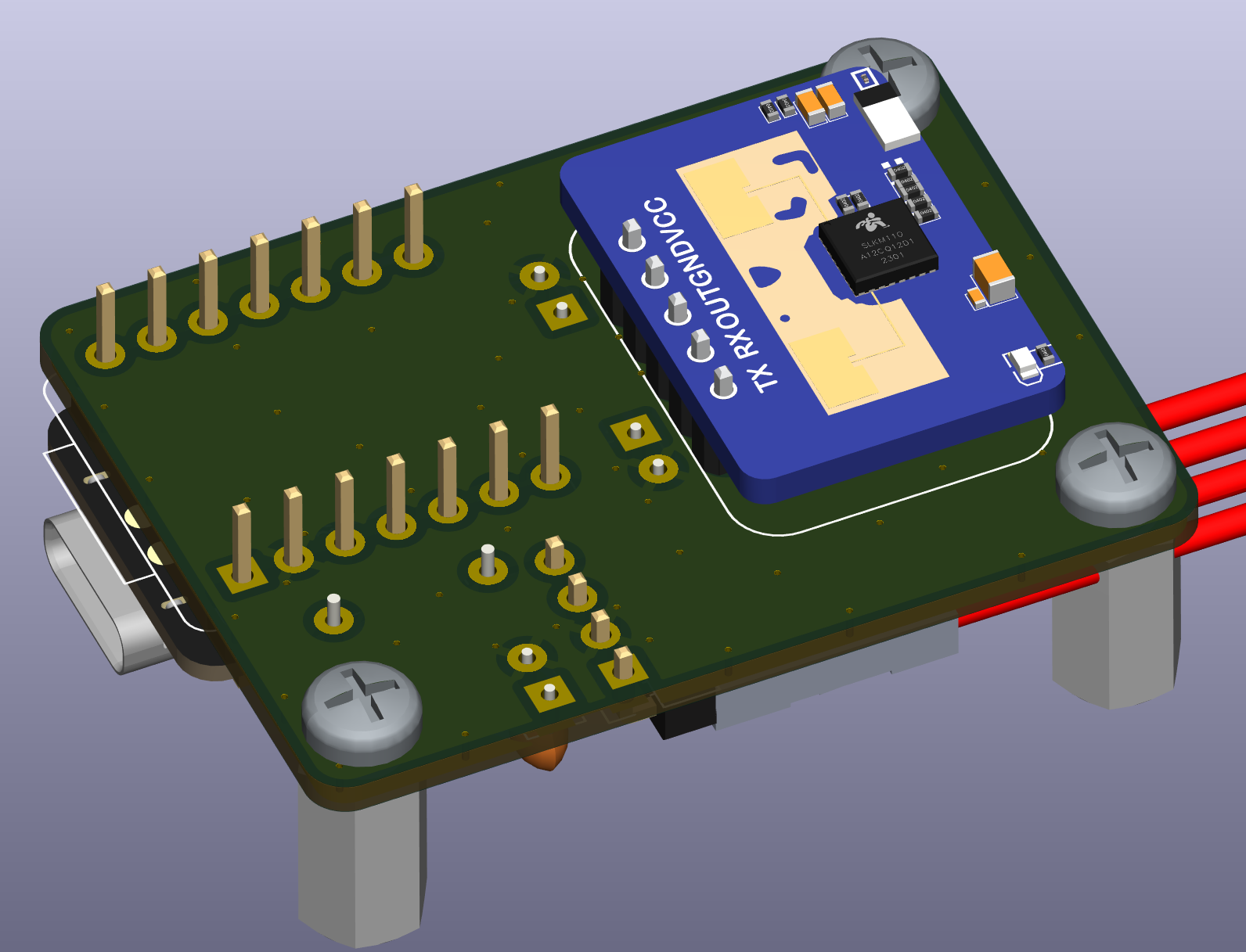
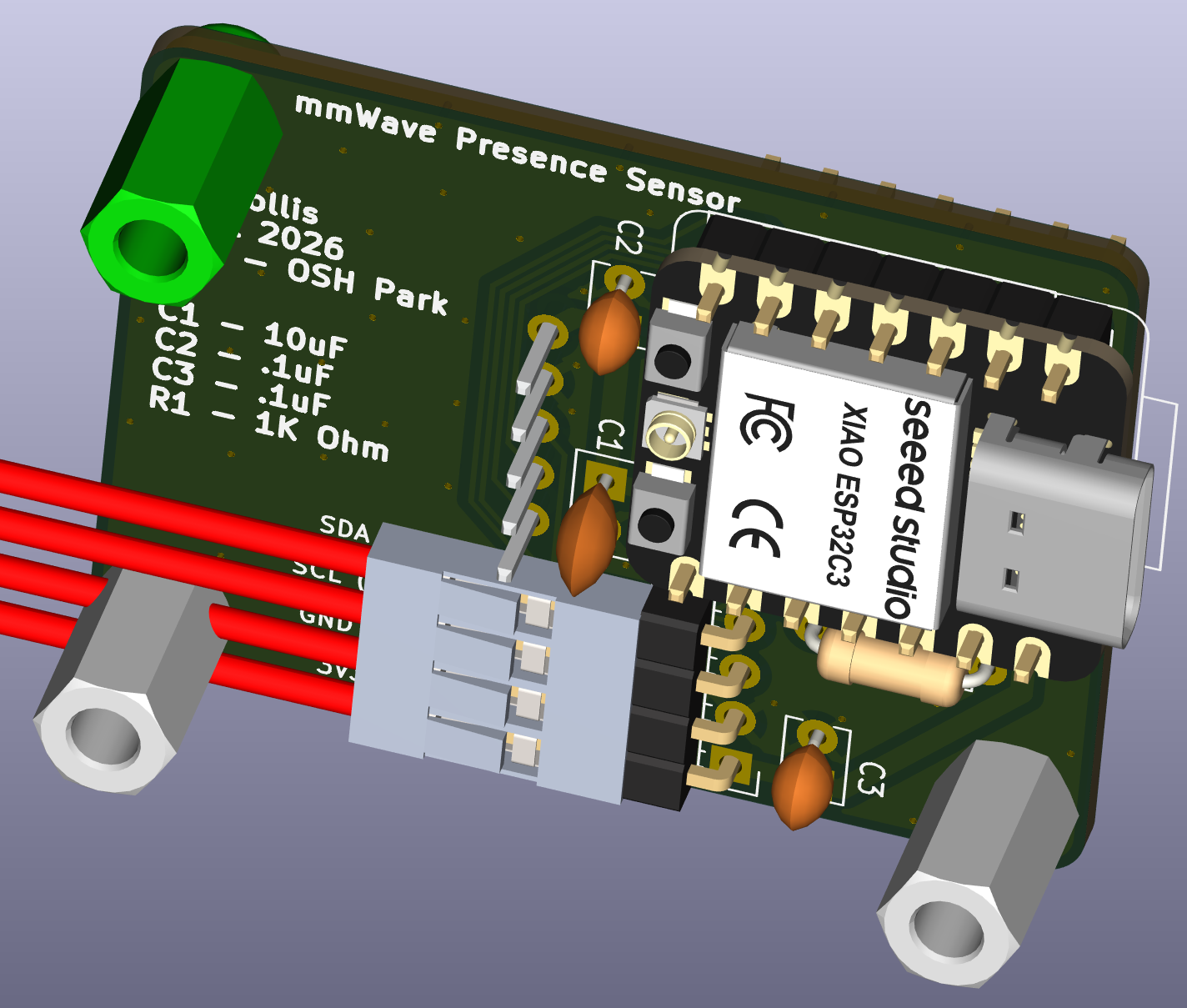
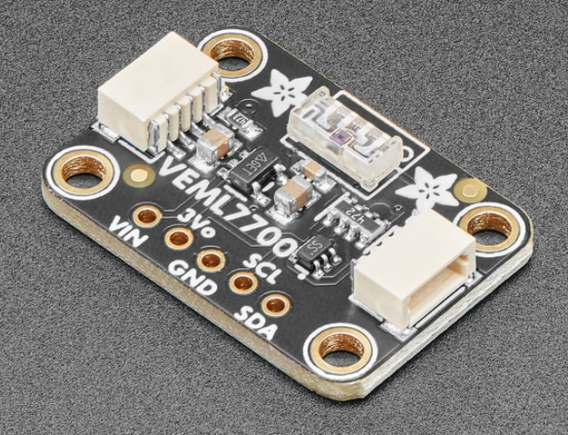
It is 23:00. The family room is dark and empty. A person walks in and sits down to read. The light comes on within one second, stays on for the next ninety minutes while they barely move, and goes off some minutes after they leave. Nobody touches a switch. Nobody is available to fix anything.
That is the acceptance test, not "99.9% uptime". A node that is powered and online but drops the still-target at minute forty has failed the moment of demand — and so has one that takes three seconds to notice someone walked in. The reasoning behind every threshold, and the measurements that set them, are in docs/mmwave-presence-node-design.md.
| Design document | Rev 1.11, October 2026 |
| PCB | Fabricated and populated. 44.0 × 33.0 mm, 2-layer, three built |
| Bench validation | First session against real hardware 2026-09-07 — seven corrections and one retraction folded back into Rev 1.6. 14.5 days of bench data reviewed 2026-09-22 — folded into Rev 1.7 |
| Firmware / HA config | Deployed. Both nodes run firmware 0.4. The whole package (office and family room) is live in Home Assistant, derived from packages/mmwave_presence.yaml |
| Deployment | Office live since 2026-09-26, family room since 2026-10-02. First production review 2026-10-16, folded into Rev 1.8. A lamp lit into an empty room goes off after 5 min, from Rev 1.9 (2026-10-16). Family lamps the package lit go off on a bright morning, sunrise to noon, from Rev 1.10 (2026-10-19). Family lamps hold while the TV is on, from Rev 1.11 (2026-10-23) |
| Latency (R2) | Family room: median 0.386 s, P95 0.409 s, n=103 [M] (HA's timestamps, presence edge → lamp relay on; not photons). Office: median 2.404 s, P95 6.769 s, n=68 [M]. That is not met by design: the office lamp waits until the person is inside the approach limit, so a walk from the doorway is in the figure. Before that filter it was median 0.387 s, n=25 [M] — design doc §8 |
| Known fault | The office node loses power every night, about 23:30 to 07:00 [M: 13 nights, 09-29 → 10-12], and was dark for 79.66 h on 10-12 → 10-15 [M]. Under the §7 "lamp stays on while the node is offline" rule, the lamp stayed lit through 6 of those nights, 47.06 h in all [M]. Cause (owner, 2026-10-16): the node's outlet strip is fed by the Kasa computer outlet, which goes off overnight; the outlet's off-spans match all 14 dark gaps [M]. The remedy is the owner's call — design doc §9 item 16 |
The design document's §0 recorded what was its most consequential open question:
the 5.6 m detection target and the gate-2 (7.4 ft) cap needed to reject a person
in the next room cannot both hold. It is closed (owner-confirmed 2026-10-23), and
neither is kept for the office. The 5.6 m target is a family-room requirement only
(design doc §3.6); that node runs max gate 8. The office rejects the bathroom next
door in Home Assistant instead: occupancy starts only on a target reported inside
82 in (owner, 2026-10-16), live since 2026-09-27 as the P24 filter in
packages/mmwave_presence.yaml. A gate-2 cap was rejected because the doorway
reads at gate 3 too, so it would read a person standing there as empty. The office
radar still runs placeholder gates (move 4, still 4) until they are measured at the
mount (design doc §9 item 11).
docs/          Design document, draft notes, the LD2410C documentation review,
               and the Hi-Link / Adafruit primary sources they cite
hardware/      KiCad 10 board, 3D models, gerbers, enclosure DXF, BOM
esphome/       Node firmware — common config plus per-node overlays
packages/      Home Assistant package: the control logic and its helpers
dashboards/    Home Assistant views for commissioning and monitoring
scripts/       Calibration and config-checking tools
assets/ Photos of the built nodeesphome/, packages/, dashboards/ and scripts/ deliberately mirror the
layout under Home Assistant's /config, so a path named in the notes means the
same thing here and on the target.
| Board | 44.0 × 33.0 mm, 2-layer, 1 oz copper, 1.6 mm FR4 |
| Front copper | Pads and vias only, no traces — unbroken ground plane under the radar |
| Back copper | All routing. 1 mm power, 0.25 mm signal, 0.2 mm clearance |
| Mounting | 3 × M3 NPTH; H2 and H3 sit under U2's courtyard by design — use nylon fasteners |
| Vias | 67 total, 16 under the module, largest gap 5.39 mm (below λg = 5.96 mm) |
1 oz / 1.6 mm, not 2 oz / 0.8 mm. At 24.125 GHz the skin depth is 0.425 µm, so 1 oz is already 82 skin depths and 2 oz buys nothing electrically. 0.8 mm has 1/8 the flexural rigidity, which is the wrong direction for a vertically mounted board carrying a cantilevered radar where flex changes the antenna-to-window distance.
Module pin order, printed on the antenna face: TX RX OUT GND VCC.
| LD2410C | Signal | Direction | XIAO | GPIO |
|---|---|---|---|---|
| 1 | UART_Tx | module → ESP | D3 | GPIO5 |
| 2 | UART_Rx | ESP → module | D2 | GPIO4 |
| 3 | OUT | module → ESP | D10 | GPIO10 (via R1) |
| 4 | GND | — | GND | — |
| 5 | VCC | 5 V in | VBUS, not 3V3 | — |
Identify every pin by its silkscreen label, never by position or number. VCC and TX sit at opposite ends of a five-pin header, so counting from the wrong end puts 5 V on TX. That is the one wiring error on this module that destroys something.
| pad | label | XIAO | GPIO |
|---|---|---|---|
| 1 | 3V3 (RED) | 3V3 | — |
| 2 | GND (BLACK) | GND | — |
| 3 | SCL (YELLOW) | D5 | GPIO7 |
| 4 | SDA (BLUE) | D4 | GPIO6 |
The colours match the Qwiic/STEMMA QT convention. The pin order deliberately does not — it was chosen for cleaner routing, and the silkscreen colour labels are the interface instead.
Build constraint: only a flying-lead QT cable works
Adafruit 4397 terminates in four independent female sockets, so each wire is placed by colour. A molded 4-pin housing cable connects power backwards and destroys the sensor. The board tells you the colours but not why.
Cut the VEML7700's power-LED jumper before the sensor goes near the enclosure. The Adafruit 4162 carries a green power LED on the same face as the photodiode. This is a sealed box: an ambient-light sensor locked in the dark with its own light source is partly measuring that source, and because the offset is constant it presents as a calibration rather than a fault.
The light sensor is off-board on a 150 mm cable, by design. On-carrier it sat 3.41 mm from the module edge — a near-field problem — and it could not be aimed independently of the radar.
Open hardware/mmWave Presence Lighting Node.kicad_pro in KiCad 10. All in-repo
3D models resolve through ${KIPRJMOD}/3d/, so a fresh clone renders the full
assembly with no path fixing.
Two things to know before you file a bug against the board:
There is no schematic. The project is board-only, so KiCad cannot run connectivity or clearance DRC against a netlist — every error across seven revisions was found by reading coordinates. Building the schematic is open item §9.5 and is the one gate still running on human attention. Corrected 2026-09-22: too strong. The pads carry net assignments, so DRC's connectivity check does run against the board's own nets — that is the "0 unconnected items" below. What is missing is an independent schematic to check those nets against.
kicad-cli pcb drc reports 16 violations, and that is the expected baseline —
3 errors, 13 warnings, 0 unconnected items. Compare against this baseline
rather than expecting zero. It breaks down as:
| n | severity | rule | why it is accepted |
|---|---|---|---|
| 2 | error | courtyards_overlap | H2 and H3 sit under U2's courtyard by design — see §3.1 and the nylon-fastener note in §3.9 |
| 1 | error | npth_inside_courtyard | same cause: a mounting hole inside the module's courtyard |
| 4 | warning | silk_over_copper | cosmetic, reviewed |
| 2 | warning | silk_edge_clearance | cosmetic, reviewed |
| 6 | warning | lib_footprint_mismatch | stock footprints deliberately modified in place (C1 relocated for U.FL clearance, 3D models attached) |
| 1 | warning | lib_footprint_issues | U2 — its footprint is stored inline in the board with no library behind it |
Full detail, including the terms that apply to each, is in THIRD_PARTY_NOTICES.md. These files are not covered by this repository's own licences.
One file is non-commercial. The LD2410C radar mesh (
hardware/3d/LD2410C mmWave Sensor.stepand its snapshot directory) is CC BY-NC 4.0. It is a 3D viewer mesh only — it is not in the gerbers, so it does not restrict manufacturing this board. For commercial use, delete those paths and render U2 with the Hi-Link model instead.
| Asset | Origin | Note |
|---|---|---|
hardware/3d/LD2410C mmWave Sensor.step | Ben Cooney, via GrabCAD | CC BY-NC 4.0 — non-commercial; licence image ships in ld2410c-mmwave-sensor-1.snapshot.2/ |
hardware/3d/HLK-LD2410C-3D图/ | Hi-Link | Manufacturer 3D model |
hardware/3d/Adafruit VEML7700.zip | SnapMagic | Part models remain SnapMagic's intellectual property |
docs/LD2410C Docs/*.pdf | Hi-Link, Adafruit | Datasheet, serial protocol V1.07, VEML7700 guide |
hardware/3d/Seeed-Studio-XIAO-ESP32-C3.step | Seeed Studio |
Where the Hi-Link datasheet and the serial protocol document disagree, the protocol document wins: it is two years newer and it documents the commands the module obeys.
Every credential in this repository resolves through ESPHome !secret, and the
secrets.yaml those resolve against lives in the Home Assistant config, not
here. Git history has been scanned and contains no plaintext SSID, PSK, API
encryption key or OTA password in any commit.
Three licences, because this repository holds three different kinds of work:
| Content | Paths | Licence |
|---|---|---|
| Hardware design | hardware/ | CERN-OHL-S v2 |
| Code | esphome/, packages/, dashboards/, scripts/ | MIT |
| Documentation | docs/, this README | CC BY 4.0 |
See LICENSE for the full breakdown and attribution examples, and THIRD_PARTY_NOTICES.md for the vendor files that none of the above covers.
CERN-OHL-S is strongly reciprocal: build the board, sell it, modify it — but if you convey a modified design or a product made from it, the modified source has to be available under the same terms.
Copyright (C) 2026 William K. Collis

This source describes Open Hardware and is licensed under the CERN-OHL-S v2.

You may redistribute and modify this source and make products using it under
the terms of the CERN-OHL-S v2 (https://ohwr.org/cern_ohl_s_v2.txt).

This source is distributed WITHOUT ANY EXPRESS OR IMPLIED WARRANTY, INCLUDING
OF MERCHANTABILITY, SATISFACTORY QUALITY AND FITNESS FOR A PARTICULAR PURPOSE.
Please see the CERN-OHL-S v2 for applicable conditions.

Source location: https://github.com/wkcollis1-eng/mmwave-presence-node
If this design document or the commissioning method saved you time on your own presence-sensing build, sponsorship funds continued instrumentation, hardware and documentation.
| Qty | Value | Footprint | References |
|---|---|---|---|
| 3 | MountingHole_3.5mm | MountingHole:MountingHole_3.5mm | H1, H2, H3 |
| 2 | C_Disc_D3.8mm_W2.6mm_P2.50mm | Capacitor_THT:C_Disc_D3.8mm_W2.6mm_P2.50mm | C2, C3 |
| 1 | C_Disc_D5.0mm_W2.5mm_P2.50mm | Capacitor_THT:C_Disc_D5.0mm_W2.5mm_P2.50mm | C1 |
| 1 | LD2410C Sensor Module | Adafruit INA260:SeeedStudio_24gHz_mmWave | U2 |
| 1 | PinHeader_1x04_P2.54mm_Horizontal | Connector_PinHeader_2.54mm:PinHeader_1x04_P2.54mm_Horizontal | PH1 |
| 1 | R_Axial_DIN0207_L6.3mm_D2.5mm_P7.62mm_Horizontal | Resistor_THT:R_Axial_DIN0207_L6.3mm_D2.5mm_P7.62mm_Horizontal | R1 |
| 1 | SeeedStudio_XIAO_ESP32C3 | PCM_fab:SeeedStudio_XIAO_ESP32C3 | U1 |
gusmanb/logicanalyzer
24 channel, 100Msps logic analyzer hardware and software

byrantech/laptop
anyon_e, a highly integrated, high end, open source laptop. Attempt the impossible.

joeycastillo/Sensor-Watch
A board replacement for the classic Casio F-91W wristwatch


OLIMEX/OLINUXINO
OLINUXINO is Open Source / Open Hardware, low cost from EUR 24 Linux Industrial grade Single Board Computer capable to operate -25+85C

rusefi/rusefi
rusefi - GPL internal combustion engine control unit

VoronDesign/Voron-Hardware
Cool Hardware designed by the Voron Design group

hoglet67/RGBtoHDMI
Bare-metal Raspberry Pi project that provides pixel-perfect sampling of Retro Computer RGB/YUV video and conversion to HDMI
It measures 44 × 33 mm and has 2 copper layers, 1.6 mm thick.
10 parts. The full list of its parts is on this page, with links to each part's symbol and footprint where PCBKit's library has them.
From the wkcollis1-eng/mmwave-presence-node repository on GitHub, at the commit this page was made from: the board is hardware/mmWave Presence Lighting Node.kicad_pcb. PCBKit opens the board in the browser, with nothing to install.
Its repository states no licence, so its author keeps all rights: ask wkcollis1-eng before reusing the design.