

4 layers170 × 170 mm

A version of the regular PICO-AT adapter, but with momentary power switch support.
PICO AT is an open-source printed circuit board by wiretap-retro, from the wiretap-retro/PICO-AT-Power-Adapter-softpower repository on GitHub. It is a 4-layer board of 54.4 × 34.8 mm with 16 parts on 16 nets, routed with 68 tracks and 3 vias.
It is built around the MAX16054AZT+T and L7905. Its parts include 4 resistors, 3 connectors, 2 capacitors and 2 ICs. It belongs with the RP2040 boards of this library.
A version of the regular PICO-AT adapter, but with momentary power switch support.
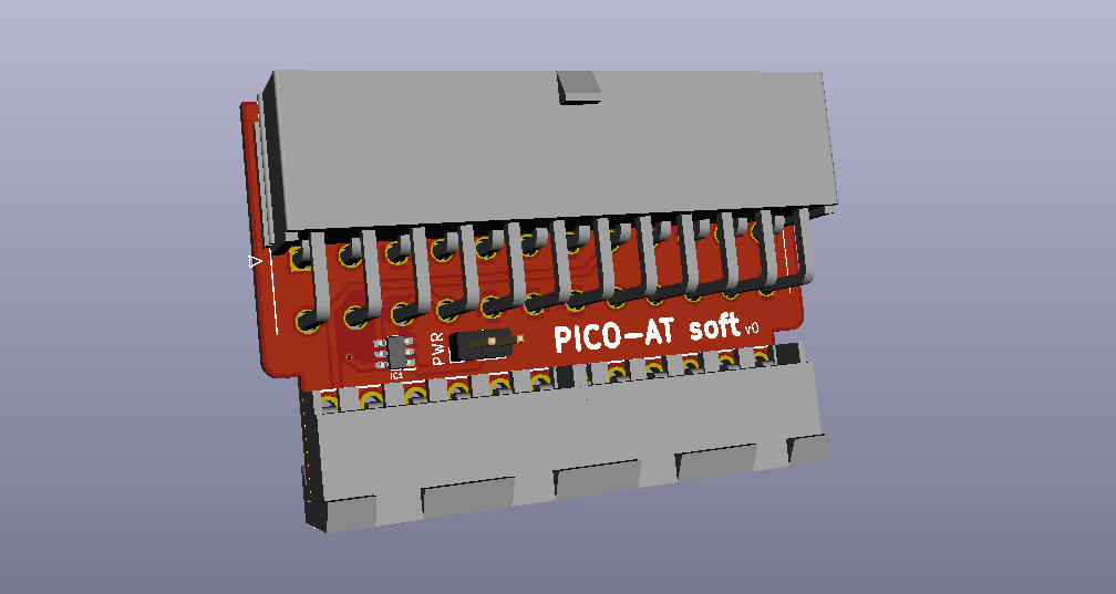
I designed this board for a small SBC that I could not fit a large power supply in the enclosure. This design is recommended for PICO-PSU units, and can be used with various retro motherboards that have the AT-style power connector. It is not recommended to pass sustained high current over 8-amps on any single power rail through this PCB. This version utilizes a power switch with momentary actuation.
Check out Vogons.org for the thread where people are building these and also modifying the design to have fan headers and other cool stuff: https://www.vogons.org/viewtopic.php?f=46&t=86465
This is an open source design. Feel free to do what you want with it.
| Qty | Value | Footprint | References |
|---|---|---|---|
| 4 | LED | LED_SMD:LED_0805_2012Metric_Pad1.15x1.40mm_HandSolder | -5V, 5V, 12V, PG |
| 3 | 330 | Resistor_SMD:R_0805_2012Metric_Pad1.15x1.40mm_HandSolder | R1, R2, R4 |
| 2 | 09-48-1064 | 09481064 | J1, J2 |
| 1 | 1k | Resistor_SMD:R_0805_2012Metric_Pad1.15x1.40mm_HandSolder | R3 |
| 1 | 1uF | Capacitor_Tantalum_SMD:CP_EIA-6032-28_Kemet-C_Pad2.25x2.35mm_HandSolder | C2 |
| 1 | 2.2uF | Capacitor_Tantalum_SMD:CP_EIA-6032-28_Kemet-C_Pad2.25x2.35mm_HandSolder | C1 |
| 1 | 87427-2402 | 87427-2402 | J3 |
| 1 | L7905 | Package_TO_SOT_THT:TO-220-3_Horizontal_TabDown | U1 |
| 1 | MAX16054AZT+T | SOT95P275X110-6N | IC1 |
| 1 | PWR_SW | Connector_PinHeader_2.54mm:PinHeader_1x02_P2.54mm_Vertical | PWR |

sensors-inl/Nervous-EDA
ECAD design files, firmware source code and standalone application for the EDA sensor of the Nervous project.

sensors-inl/Nervous-ECG
ECAD design files, firmware source code and standalone application for the ECG sensor of the Nervous project.

JHPate1/Arctiq-GPS
A Mainboard PCB design for my custom handheld navigation device.

Global-Health-Engineering/h2s-monitor
Design and Development of a Low-Cost Hydrogen Sulfide Sensor System for Biogas Monitoring


Kleavox/deltaT26-Keel
HAT tengah untuk Raspberry Pi 4: distribusi daya + hub USB3 on-board + telemetri untuk NAS 2-disk, disatukan lewat tumpukan Pi 4 → Keel → EP-0152 dengan duct 3D-print sendiri buat mendinginkan SoC.

It measures 54.4 × 34.8 mm and has 4 copper layers, 1.6 mm thick.
16 parts, built around the MAX16054AZT+T and L7905. The full list of its parts is on this page, with links to each part's symbol and footprint where PCBKit's library has them.
From the wiretap-retro/PICO-AT-Power-Adapter-softpower repository on GitHub, at the commit this page was made from: the board is PICO-AT-softpower/PICO-AT.kicad_pcb. PCBKit opens the board in the browser, with nothing to install.
Its repository states no licence, so its author keeps all rights: ask wiretap-retro before reusing the design.