4 layers65 × 35 mm
FlexiBMS
SimosMCmuffin/FlexiBMS_hardware
Open Source BMS developed by Simo Sihvonen (Simos MCmuffin) with the Esk8 community, for the Esk8 community
209 parts14

 willbicks/pdu-relay1
A 120V AC relay module to safely power down rack mount equipment when not needed.
Pdu relay is an open-source printed circuit board by willbicks, from the willbicks/pdu-relay repository on GitHub, published under the CERN-OHL-W-2.0 licence. It is a 2-layer board of 55 × 40 mm with 15 parts on 8 nets, routed with 36 tracks and 0 vias.
It is built around the IRM-01-5, 1N4448W and BSS84PW(TP). Its parts include 4 connectors, 2 resistors, 1 diode, 1 transistor and 1 switch. It belongs with the home automation and IoT boards of this library.


This PDU relay is intended to be retrofit into a standard 19" rack mount PDU, and allows for any subsection of the outputs to be turned on or off based on an external isolated logic input. It provides a relay that energizes the live rail of the PDU only when the logic input is held low, and de-energizes them otherwise. This makes the logic input suitable for any dry contact or open collector output that can sink a few milliamps of current.
In my case, I am using this module in a JG JR PDU to switch on audio amplifiers when a Biamp Tesira DSP detects audio input, and then automatically switch them back off after a period of inactivity to conserve power.
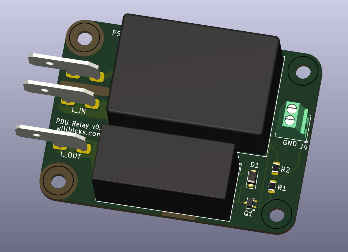
This power supply and relay in this module are rated to support:
The AC input / output terminals are 0.25" x 0.032" spade terminals.
The logic input is a 2.54mm pitch 2-pin screw terminal. Pin 1 is an AC isolated ground, while pin 2 is the active low logic input. To close the relay, pin 2 should be pulled low relative to the ground terminal. Total current draw from the logic input is less than 1 mA.
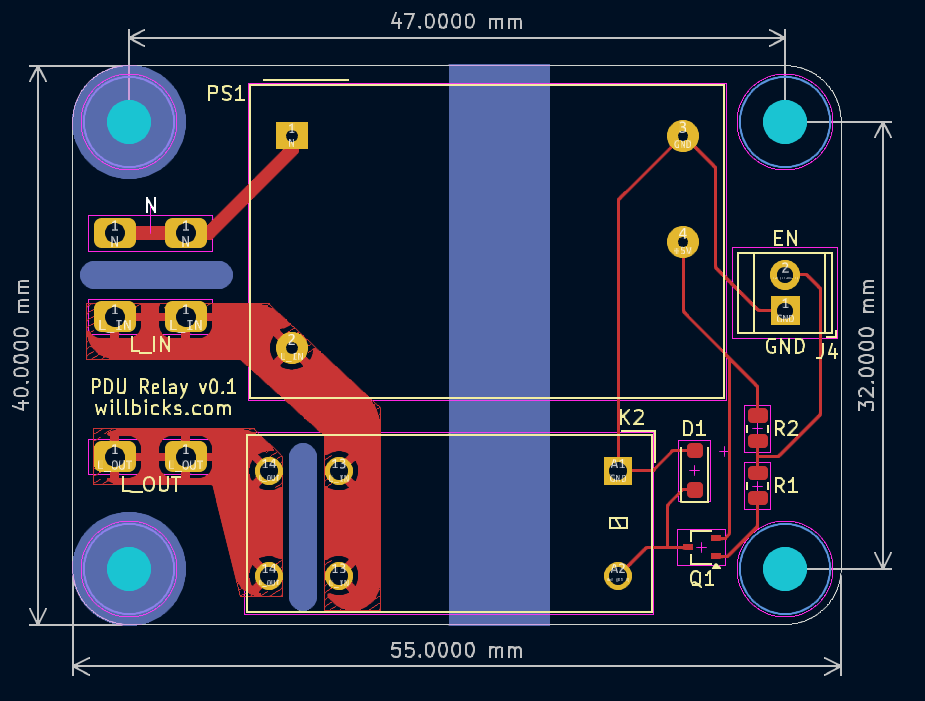
The assembled module is 55 mm x 40 mm x ~20mm. It has 4 holes for M3 screws that are 47 mm x 32 mm between centers as shown below.
This repository contains a KiCAD 8.0.0 project with the schematic and PCB layout for the PDU relay module. Gerber files, a BOM, and PDFs of the schematic and PCB layout are available in the releases section of the repository.
This unit is intended for reference and evaluation and has not been tested nor certified by any safety agency. It is the responsibility of the user to ensure that the final product meets all applicable safety standards and regulations.
In addition to ensuring that this design meets all applicable safety standards and regulations, the following basic precautions should be taken when installing and using this module:
Copyright Will Bicks 2024.
This source describes Open Hardware and is licensed under the CERN-OHLW v2 You may redistribute and modify this documentation and make products using it under the terms of the CERN-OHL-W v2 (https:/cern.ch/cern-ohl).
This documentation is distributed WITHOUT ANY EXPRESS OR IMPLIED WARRANTY, INCLUDING OF MERCHANTABILITY, SATISFACTORY QUALITY AND FITNESS FOR A PARTICULAR PURPOSE. Please see the CERN-OHL-W v2 for applicable conditions.
Source location: https://www.github.com/willbicks/pdu-relay
| Qty | Value | Footprint | References |
|---|---|---|---|
| 4 | M3 Mounting Hole | MountingHole:MountingHole_3.2mm_M3 | H1, H2, H3, H4 |
| 1 | 1N4448W | Diode_SMD:D_SOD-123F | D1 |
| 1 | 470 | Resistor_SMD:R_0805_2012Metric | R1 |
| 1 | 47k | Resistor_SMD:R_0805_2012Metric | R2 |
| 1 | BSS84PW | Package_TO_SOT_SMD:SOT-323_SC-70 | Q1 |
| 1 | EXT_ON | TerminalBlock_TE-Connectivity:TerminalBlock_TE_282834-2_1x02_P2.54mm_Horizontal | J4 |
| 1 | G2RL-1A-E DC5 | Relay_THT:Relay_SPST_Omron_G2RL-1A-E | K2 |
| 1 | IRM-01-5 | Converter_ACDC:Converter_ACDC_MeanWell_IRM-02-xx_THT | PS1 |
| 1 | LOGO | Bicks_Branding:logo_sma | G*** |
| 1 | L_IN | Connector_Spade:Keystone_4966 | J1 |
| 1 | L_OUT | Connector_Spade:Keystone_4966 | J3 |
| 1 | N | Connector_Spade:Keystone_4966 | J2 |
It measures 55 × 40 mm and has 2 copper layers, 1.6 mm thick.
15 parts, built around the IRM-01-5, 1N4448W and BSS84PW(TP). The full list of its parts is on this page, with links to each part's symbol and footprint where PCBKit's library has them.
From the willbicks/pdu-relay repository on GitHub, at the commit this page was made from: the board is pdu-relay.kicad_pcb and its schematic pdu-relay.kicad_sch. PCBKit opens the board in the browser, with nothing to install.
Its repository publishes it under the CERN-OHL-W-2.0 licence: you may reuse it on that licence's terms (keep the author's notice, and for a copyleft licence share your changes alike).
SimosMCmuffin/FlexiBMS_hardware
Open Source BMS developed by Simo Sihvonen (Simos MCmuffin) with the Esk8 community, for the Esk8 community

bugg-resources/bugg-hardware-main
This repository contains the KiCad source files for the main PCB of the Bugg recording device.


RespiraWorks/Ventilator
Fully-featured ICU ventilator design, optimized for manufacture using commonly available components and free to license.


