
6 layers190 × 140 mm

 Will946/USBC-PD
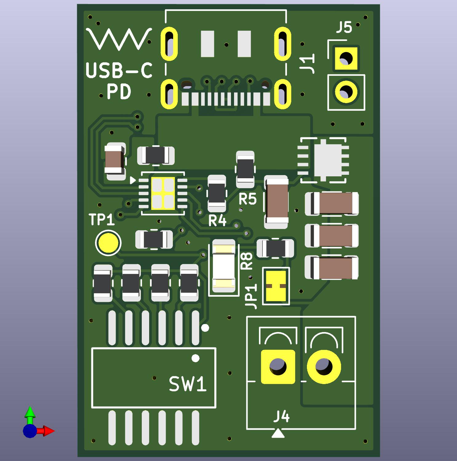
A compact USB Power Delivery sink board based on the HUSB238 USB-PD controller IC. Accepts USB-C PD input and outputs a selectable regulated voltage via an onboard 6-position DIP switch.
USCB PD is an open-source printed circuit board by Will946, from the Will946/USBC-PD repository on GitHub, published under the MIT licence. It is a 2-layer board of 23.1 × 34.5 mm with 24 parts on 23 nets, routed with 134 tracks and 41 vias.
It is built around the AONR21307. Its parts include 9 resistors, 5 capacitors, 3 connectors, 1 diode and 1 switch. It belongs with the power boards of this library.
A compact USB Power Delivery sink board based on the HUSB238 USB-PD controller IC. Accepts USB-C PD input and outputs a selectable regulated voltage via an onboard 6-position DIP switch. Designed as a cleaner, improved implementation of the Adafruit USB Type-C Power Delivery Dummy Breakout, with a fixed 3A current request, soft-start capacitor, and SMD components throughout.
| Parameter | Value |
|---|---|
| Input Interface | USB-C PD 3.0 / Type-C v1.4 |
| Input Voltage Range | 3V – 25V (VBUS) |
| Max Output Power | 100W (20V × 5A) |
| Requested Output Current | 3A (fixed via R9 = 22.6KΩ) |
| Output Voltage | Selectable via DIP switch (see below) |
| Controller IC | HUSB238_xxxDD |
| MOSFET | AONR21307 (DFN8 3×3mm) |
| Legacy Protocol Support | Apple Divider 3, BC1.2 (SDP, CDP, DCP) |
| PCB Layers | 2 |
| Designed With | KiCad 9.0 |
Output voltage is set by closing one switch at a time on SW1. Each switch connects a resistor between the HUSB238 VSET pin and GND. The HUSB238 reads the resulting voltage on VSET (set by a 100µA internal current source through the resistor) and negotiates the corresponding PD voltage profile with the USB-C adapter.
Only one switch should be ON at a time. Closing multiple switches places resistors in parallel, which will result in an unintended voltage being requested.
| SW1 Position | Resistor | VSET Resistance | Requested Voltage | Max Power @ 3A |
|---|---|---|---|---|
| SW1-1 | R1 (6K) | 6.04KΩ | 9V | 27W |
| SW1-2 | R2 (10K) | 10KΩ | 12V | 36W |
| SW1-3 | R6 (14K) | 14KΩ | 15V | 45W |
| SW1-4 | R7 (18K) | 17.8KΩ | 18V | 54W |
| SW1-5 | — | 0Ω (short to GND) | 5V | 15W |
| SW1-6 | — | NC (open) | 20V | 60W |
How voltage selection works: The HUSB238 requests a voltage equal to or lower than the programmed value. If the connected USB-C adapter does not support the requested voltage (e.g. a strict PD adapter with no 12V profile), the board will fall back to the next lower available voltage (e.g. 9V). Always verify the output voltage with a multimeter before connecting a load.
Important: If no switch is closed (all OFF), the VSET pin floats and the HUSB238 defaults to requesting 20V. Ensure a known switch position is set before powering up.
The output current request is fixed at 3A via R9 (22.6KΩ) connected between the ISET pin and GND. This is hardwired on the board and cannot be changed without reworking R9.
The HUSB238 will request 3A from the adapter. If the adapter cannot supply 3A at the negotiated voltage, it will supply whatever current it is rated for — the board will not be damaged, but the load current must not exceed the adapter's rating.
| ISET Resistor | Requested Current |
|---|---|
| 0KΩ | 1.25A |
| 4.53KΩ | 1.5A |
| 7.5KΩ | 1.75A |
| 10.5KΩ | 2A |
| 13.7KΩ | 2.25A |
| 16.5KΩ | 2.5A |
| 19.6KΩ | 2.75A |
| 22.6KΩ (R9, fitted) | 3A |
| NC | 3.25A |
USB-C VBUS → 10Ω series resistor (R3) → VIN pin of HUSB238 → HUSB238 drives GATE pin → AONR21307 MOSFET → VOUT
The MOSFET acts as a load switch controlled by the HUSB238. It only turns on after a successful PD contract is established. R4 (5.1KΩ) sits on the GATE line, and R5 (49.9KΩ) pulls the MOSFET source to VBUS to ensure proper biasing.
The 6 DIP switch positions each connect a different resistor to the VSET bus. All resistor pad 1s share the VSET bus; pad 2 of each resistor goes to its own DIP switch pin, which connects to GND when closed. TP1 is connected to this VSET bus and can be probed to verify the set voltage level.
Three 4.7µF capacitors (C2, C3, C4) on the output reduce ripple and improve transient response. C1 (1µF) decouples the HUSB238 VIN pin.
D1 (LED) is connected to VOUT via R8 (49.9KΩ) and JP1 (solder jumper). JP1 is bridged by default — cut the trace to disconnect the LED. The LED illuminates when output voltage is present.
The HUSB238 supports I2C at address 0x08 for dynamic voltage/current control and source capability querying. J5 exposes the SCL and SDA lines. Note: I2C requires external pullup resistors to the logic level of the connected microcontroller. I2C settings override the DIP switch resistor settings.
| Ref | Type | Pitch | Description |
|---|---|---|---|
| J1 | USB-C 16P Receptacle | — | USB-C PD input (JAE DX07S016JA1R1500) |
| J4 | Screw Terminal 1×02 | 3.5mm | Power output — VOUT and GND |
| J5 | Pin Header 1×02 | 2.54mm | I2C (SCL, SDA) / auxiliary output |
| Ref | Value | Package | Description |
|---|---|---|---|
| C1 | 1uF/50V | 0805 | VIN decoupling capacitor |
| C2, C3, C4 | 4.7uF/50V | 1206 | Output filter capacitors |
| C5 | 100nF/50V | 1206 | GATE soft-start capacitor |
| D1 | LED | 1206 | Output status indicator |
| J1 | USB_C_Receptacle_USB2.0_16P | — | USB-C input connector |
| J4 | Screw_Terminal_01x02 | P3.5mm | Output screw terminal |
| J5 | Conn_01x02 | P2.54mm | I2C / auxiliary header |
| JP1 | SolderJumper_2_Bridged | — | LED enable jumper (bridged by default) |
| MOSFET1 | AONR21307 | DFN8 3×3mm | N-channel load switch MOSFET |
| R1 | 6K | 0805 | VSET resistor → 9V |
| R2 | 10K | 0805 | VSET resistor → 12V |
| R3 | 10R | 0805 | VIN series filter resistor |
| R4 | 5.1K | 0805 | GATE resistor |
| R5 | 49.9K | 0805 | MOSFET source pullup |
| R6 | 14K | 0805 | VSET resistor → 15V |
| R7 | 18K | 0805 | VSET resistor → 18V |
| R8 | 49.9K | 0805 | LED current limit resistor |
| R9 | 22.6K | 0805 | ISET resistor → 3A current request |
| SW1 | SW_DIP_x06 | SMD P=1.27mm | 6-position voltage selection DIP switch |
| TP1 | TestPoint | Pad D1.5mm | VSET bus test point |
| U1 | HUSB238_xxxDD | WDFN-10 3×3mm | USB-PD sink controller IC |
| File | Description |
|---|---|
USCB-PD.kicad_sch | KiCad schematic |
USCB-PD.kicad_pcb | KiCad PCB layout |
USCB-PD.kicad_pro | KiCad project file |
USCB-PD.jpg | Board render |
| Qty | Value | Footprint | References |
|---|---|---|---|
| 3 | 4.7uF | Capacitor_SMD:C_1206_3216Metric | C2, C3, C4 |
| 2 | 49.9K | Resistor_SMD:R_0805_2012Metric | R5, R8 |
| 1 | 10 | Resistor_SMD:R_0805_2012Metric | R3 |
| 1 | 100nF | Capacitor_SMD:C_1206_3216Metric | C5 |
| 1 | 10K | Resistor_SMD:R_0805_2012Metric | R2 |
| 1 | 14K | Resistor_SMD:R_0805_2012Metric | R6 |
| 1 | 18K | Resistor_SMD:R_0805_2012Metric | R7 |
| 1 | 1uF | Capacitor_SMD:C_0805_2012Metric | C1 |
| 1 | 22.6K | Resistor_SMD:R_0805_2012Metric | R9 |
| 1 | 5.1K | Resistor_SMD:R_0805_2012Metric | R4 |
| 1 | 6K | Resistor_SMD:R_0805_2012Metric | R1 |
| 1 | AONR21307 | AONR21307:DFN8_3x3_EP_AOS | MOS |
| 1 | Conn_01x02 | Connector_PinHeader_2.54mm:PinHeader_1x02_P2.54mm_Vertical | J5 |
| 1 | HUSB238_xxxDD | Package_DFN_QFN:WDFN-10-1EP_3x3mm_P0.5mm_EP1.8x2.5mm | HUSB |
| 1 | LED | LED_SMD:LED_1206_3216Metric | D1 |
| 1 | LOGO | LOGO | G*** |
| 1 | SW_DIP_x06 | Button_Switch_SMD:DSHP06TS-S | SW1 |
| 1 | Screw_Terminal_01x02 | TerminalBlock_4Ucon:TerminalBlock_4Ucon_1x02_P3.50mm_Vertical | J4 |
| 1 | SolderJumper_2_Bridged | Jumper:SolderJumper-2_P1.3mm_Bridged_Pad1.0x1.5mm | JP1 |
| 1 | TestPoint | TestPoint:TestPoint_Pad_D1.5mm | TP1 |
| 1 | USB_C_Receptacle_USB2.0_16P | Connector_USB:USB_C_Receptacle_JAE_DX07S016JA1R1500 | J1 |
It measures 23.1 × 34.5 mm and has 2 copper layers, 1.6 mm thick.
24 parts, built around the AONR21307. The full list of its parts is on this page, with links to each part's symbol and footprint where PCBKit's library has them.
From the Will946/USBC-PD repository on GitHub, at the commit this page was made from: the board is USCB-PD.kicad_pcb and its schematic USCB-PD.kicad_sch. PCBKit opens the board in the browser, with nothing to install.
Its repository publishes it under the MIT licence: you may reuse it on that licence's terms (keep the author's notice, and for a copyleft licence share your changes alike).

CubeSource/Burnwing
A burnwire release mechanism development board. Featherwing form factor.

xx0x/nano-supply
Compact open source Eurorack USB-C power supply.


MicroLind-Developers/microlind-hw
Hardware repository for the microlind project