2 layers40.5 × 71 mm

 Will946/O-hareAir1
An ESP32-based flower that measures air quality with real sensors and physically points a needle at how badly you need to open a window.
OhareV1 is an open-source printed circuit board by Will946, from the Will946/O-hareAir repository on GitHub, published under the MIT licence. It is a 2-layer board of 87.2 × 69 mm with 39 parts on 50 nets, routed with 175 tracks and 115 vias.
It is built around the ENS161-BLGT, ENS210-LQFM and MCP1700T-1802E/TT(MS), with the BSS138 and IN-PI15TAT5R5G5B among its other parts. Its parts include 6 capacitors, 5 resistors, 3 ICs, 3 connectors and 1 diode. It belongs with the sensors and measurement boards and the ESP32 boards of this library.



A desktop air quality monitor shaped like a flower. It watches temperature, humidity, and air quality (eCO2/eTVOC/AQI-UBA) with a ScioSense ENS161 + ENS210, points a physical stepper-driven needle at the current rating, glows green-to-red through an RGB LED, and serves a full live dashboard over Wi-Fi with history and CSV export. No app, no cloud, no account.
The name is taken from The Lorax (2012). In the film, Aloysius O'Hare is the mayor of Thneedville and the founder/CEO of "O'Hare Air," a company that sells bottled air to the town after industrial pollution ruined the natural air supply. This project borrows the name "O'Hare Air" for a device that measures real air quality.
        ENS210 (temp/RH) ──┐
                            ├──► ESP32 ──► 28BYJ-48 stepper ──► needle (0°-180°)
        ENS161 (AQI-UBA,   ─┘      │
        eTVOC, eCO2)               ├──► RGB LED (green → yellow → orange → red)
                                    │
                                    └──► Wi-Fi ──► built-in web dashboard
                                              (Live / History / Needle tabs)
Both sensors sit on the same I2C bus. Every reading cycle, the firmware pulls temperature and humidity from the ENS210, feeds them to the ENS161 as environmental compensation (metal-oxide gas sensors need to know how hot and humid the air is to interpret resistance changes correctly), then reads the ENS161's eTVOC, eCO2, and AQI-UBA registers. AQI-UBA, the sensor's own 1-5 classification, is what drives the needle and the LED. Everything is also pushed out over the board's Wi-Fi web server so it's watchable from a phone or laptop in real time.
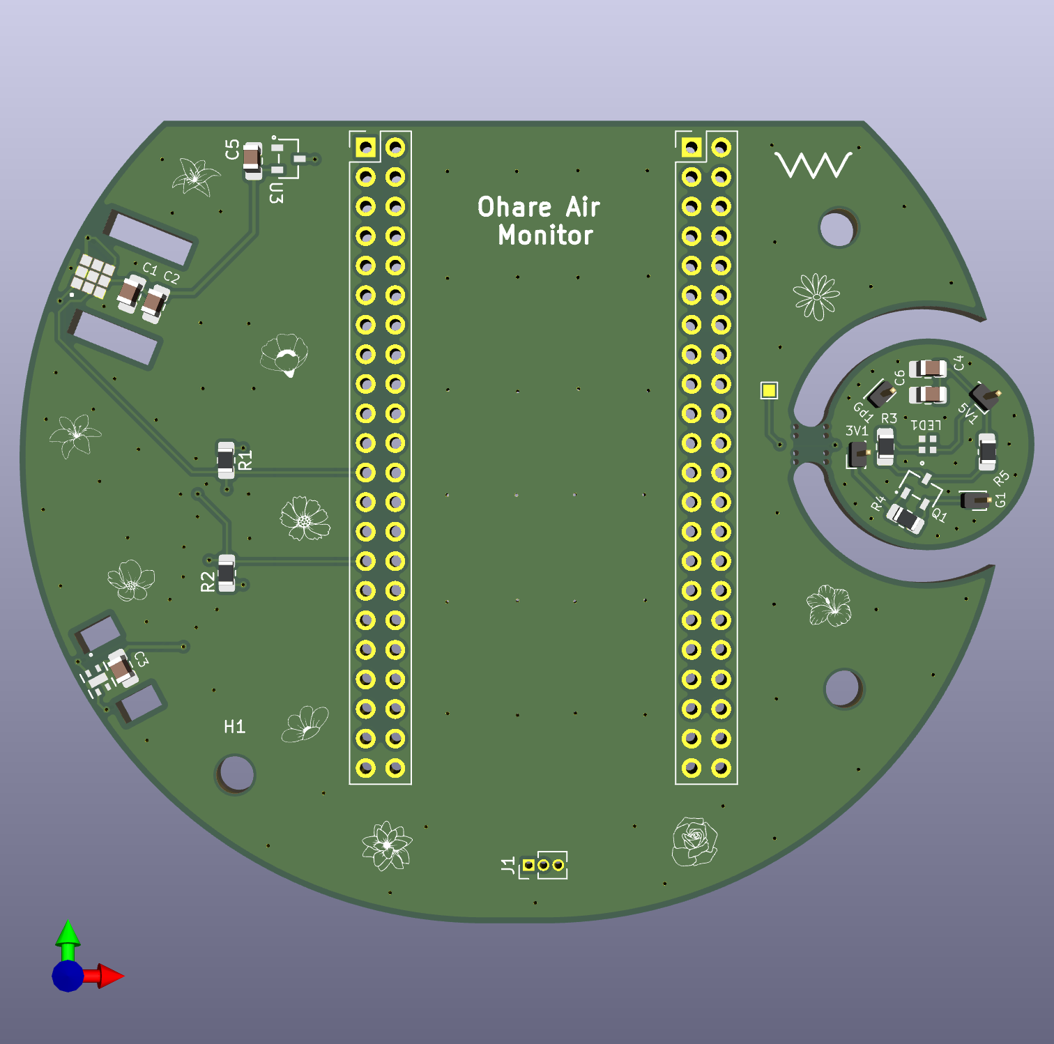
V1 is a shield: a round board with two 2×22 headers (J9/J10) that plug directly onto an ESP32-S3-DevKitC-1 dev board, using its pinout exactly. Rather than design a whole MCU circuit, V1 borrows the dev board's regulator, USB-to-serial bridge, and antenna, so the custom PCB only has to carry the sensors, the LED driver, and a 1.8 V rail.
On the shield itself:
| Ref | Part | Purpose |
|---|---|---|
| U1 | ENS161-BLGT | Air quality sensor (I2C 0x52), eTVOC, eCO2, AQI-UBA |
| U2 | ENS210-LQFM | Temperature/humidity sensor (I2C 0x43) |
| U3 | MCP1700T-1802E | Linear regulator, 3.3 V → 1.8 V for the ENS161's VDD rail |
| R1, R2 | 10 kΩ | I2C pull-ups (SCL/SDA) |
| C1–C6 | 0.1 µF / 10 µF | Decoupling for the sensors and the LED |
| Q1 | BSS138 | N-MOSFET level shifter, 3.3 V logic → 5 V for the LED data line |
| LED1 | IN-PI15TAT5R5G5B | A single addressable RGB LED |
| J1 | 3-pin socket | Breaks out 5 V / 3.3 V / LED data for the LED module |
| H1–H3, TP1 | — | Mounting holes and a test point |
The two headers expose every GPIO the dev board offers, but the sketch only actually uses a handful of them: GPIO8/GPIO9 for I2C, GPIO4–GPIO7 for the stepper's four ULN2003 driver inputs, and GPIO48 for the dev board's own onboard RGB LED.
Full schematic: OhareV1PCB/OhareV1Sch.pdf. Manufacturing files (Gerbers) are in OhareV1PCB/Gerber.zip; KiCad source is OhareV1.kicad_pcb / OhareV1.kicad_sch.
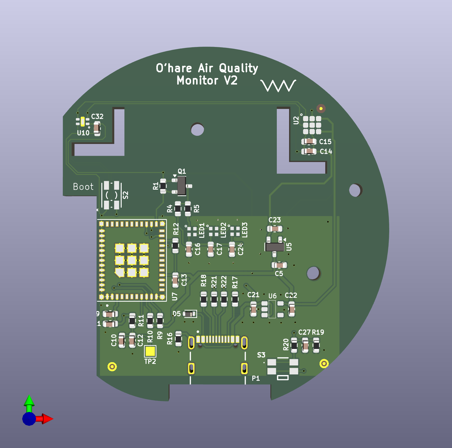
V2 throws out the dev board entirely. Instead of two headers plugging into someone else's board, V2 puts an ESP32-H2-MINI-1 module (a tiny, low-power Espressif module, not a full development board) directly on the PCB, along with its own USB-C connector and its own power regulation. The result is dramatically smaller: the whole "computer" fits in the footprint of the module itself, not a full dev-board-shaped hole in the middle of the design.
On the V2 board:
| Ref | Part | Purpose |
|---|---|---|
| U7 | ESP32-H2-MINI-1 | The microcontroller: BLE + 802.15.4 (Zigbee/Thread) radio, no Wi-Fi (see below) |
| U2 | ENS161 | Air quality sensor (I2C 0x52) |
| U10 | ENS210 | Temperature/humidity sensor (I2C 0x43) |
| U6 | AP2205 | 3.3 V regulator (the board's main "3V3 bus") |
| U5 | AP2120 | 1.8 V regulator, for the ENS161's VDD |
| P1 | USB-C receptacle | Power and native USB flashing (the H2 has built-in USB, no separate USB-serial chip needed) |
| D5 | TPD1E10B06 | ESD/surge protection on the USB data lines |
| R21, R22 | 5.1 kΩ | USB-C CC pull-downs, so the board correctly identifies itself as a 5 V sink to chargers and power banks |
| Q1 | BSS138 | Same level-shifting job as V1: 3.3 V logic to 5 V LED data |
| LED1, LED2, LED3 | IN-PI15TAT5R5G5B | Three addressable RGB LEDs (labeled Front Left / Front Right / Rear Right on the silkscreen), daisy-chained, instead of V1's single LED |
| S2 | Push button | BOOT (bootloader entry for flashing) |
| S3 | Push button | Reset |
Full schematic: OhareV2PCB/OhareV2Sch.pdf; KiCad source is OhareV2.kicad_pcb / OhareV2.kicad_sch.
| V1 | V2 | |
|---|---|---|
| MCU | ESP32-S3-DevKitC-1 (full dev board, plugged in via headers) | ESP32-H2-MINI-1 (bare module, soldered directly to the PCB) |
| Radio | Wi-Fi + BLE | BLE + 802.15.4 (Zigbee/Thread); no Wi-Fi |
| Size | Dev-board-sized | A fraction of that; the module is the board |
| Power in | Through the dev board's own USB-C | Native USB-C directly on the PCB |
| LEDs | 1 (drives the dev board's onboard LED) | 3, individually placed under the enclosure's petals |
| Flashing | Dev board's onboard USB-to-serial bridge | Native USB on the H2 itself |
| Firmware status | Fully supported, this is what the current sketch targets | **Current firmware is supported on new version |
The active firmware is Code/OhareAir/OhareAir.ino, an Arduino sketch built for the ESP32-S3 (V1). It's written directly against the ENS161 and ENS210 datasheets: talking to both sensors over I2C, driving the stepper needle and RGB LED, and serving the whole web dashboard, all from a single self-contained sketch.
On power-up, both sensors initialize immediately, but nothing is read for the first 3 minutes. The ENS161 needs that long to reach a stable operating temperature; reading it earlier just produces noise. During this warm-up the LED pulses a slow blue instead of showing a color it can't back up yet, and the needle stays parked at 0°.
Once warm-up ends, the firmware takes one reading per minute. A flower on a desk doesn't need second-by-second air-quality updates, and a slower cadence keeps the I2C bus quieter.
Each reading cycle:
TEMP_IN / RH_IN), so its gas readings account for the current conditions.The ENS161 is a metal-oxide gas sensor: it doesn't count individual VOC molecules, it measures how much a heated sensing element's electrical resistance shifts when exposed to reactive gases, then converts that into three numbers over I2C:
eTVOC (equivalent Total Volatile Organic Compounds, in ppb): the chip's estimate of total VOC concentration, calibrated against ethanol as a reference gas. This is the sensor's actual measurement; everything else is derived from it.
eCO2 (equivalent CO2, in ppm): not a real CO2 measurement. It's estimated from the same VOC signal, so it tracks eTVOC almost exactly and should be read as "how stale does the air smell," not literal CO2 concentration.
AQI-UBA (1-5): the chip's own onboard hygienic rating, computed internally by ScioSense's proprietary algorithm from its eTVOC signal, using threshold bands published by Germany's Federal Environmental Agency (Umweltbundesamt, hence "UBA"):
| AQI-UBA | Rating | Approx. eTVOC |
|---|---|---|
| 1 | Excellent | 0 – 65 ppb |
| 2 | Good | 65 – 220 ppb |
| 3 | Moderate | 220 – 650 ppb |
| 4 | Poor | 650 – 2,200 ppb |
| 5 | Unhealthy | 2,200 ppb+ |
AQI-UBA is what drives the needle and the LED, rather than a hand-built formula. eTVOC and eCO2 are still read, displayed, and logged, but the rating itself comes straight from the ENS161's own proprietary onboard algorithm: ScioSense's classification, computed inside the chip from its own internal, self-compensating signal, not something calculated in software afterward. The trade-off is that AQI-UBA can't be corrected or offset after the fact the way a software-calculated number could; whatever the chip decides, the firmware trusts.
Raw ENS210 output is corrected by a fixed offset (TEMP_OFFSET_C, currently 5.56 °C) to account for the board's own self-heating from the MCU and Wi-Fi radio; an uncorrected reading on this hardware runs noticeably warmer than the actual room. This is a per-board constant; if you build your own, re-measure it against a reference thermometer and adjust.
A 28BYJ-48 stepper motor (through a ULN2003 driver board) sweeps a needle across a 180° arc:
| Rating | Angle |
|---|---|
| Excellent | 0° |
| Good | 90° |
| Moderate | 115° |
| Poor | 140° |
| Unhealthy | 180° |
To avoid the needle twitching back and forth when AQI-UBA hovers right at a boundary, a new rating has to show up in two readings in a row (about two minutes) before the needle actually moves. Position is tracked in software as a step count from a zeroed home position. There's no physical limit switch, so the needle has to be manually set to 0° before every power-up; if the board resets while the needle is elsewhere, the software's idea of "0°" and the needle's real position will disagree until it's re-zeroed by hand.
The LED (a single onboard RGB LED on V1; three chained LEDs, wired for that, on V2's hardware) fades smoothly between colors rather than snapping: green at AQI-UBA 1, sliding through yellow and orange, to red at AQI-UBA 5. During warm-up, before any reading exists, it pulses a slow blue instead. Brightness (0/10/30/60/100%) is adjustable from the dashboard and resets to 60% on every reboot; it isn't saved to flash.
Every 5 minutes, the firmware saves one entry (the minimum, average, and maximum of temperature, humidity, AQI-UBA, eCO2, and eTVOC over that window) into a ring buffer sized for 7 days (2,016 entries), packed into a fixed 32-byte record per entry. This history lives entirely in RAM, not flash; it's lost on every reboot or power cycle. A window where a sensor read failed is stored as an explicit "no data" marker rather than a guessed value, so a bad reading never silently drags down an average.
The board runs its own web server (WebServer.h) and serves a self-contained single-page dashboard: no external app, no cloud round-trip. Connect it to Wi-Fi, open its IP address in a browser, and you get three tabs:
Live
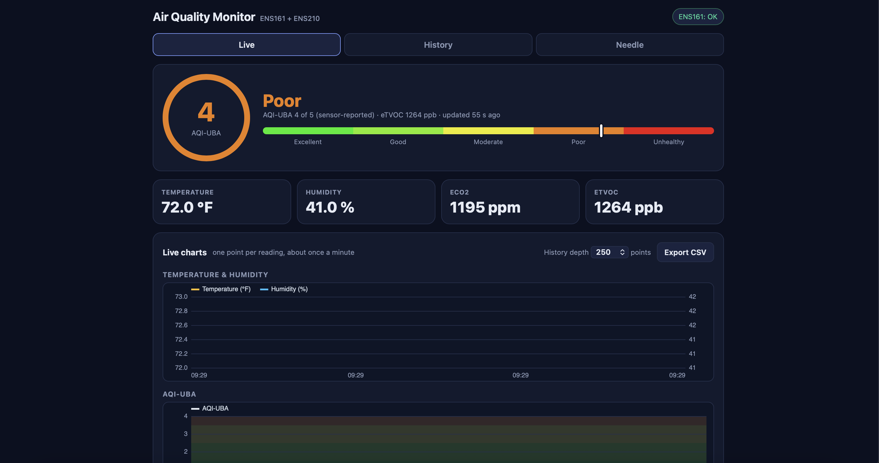
The current AQI-UBA rating as a big color-coded number and name, a five-segment scale showing where it sits, temperature/humidity/eCO2/eTVOC cards, and three live-updating charts (temperature & humidity, AQI-UBA, and gas levels) that add one point per new reading, not per page refresh, so leaving the tab open doesn't flood the chart with duplicate points. LED brightness controls live here too.
History
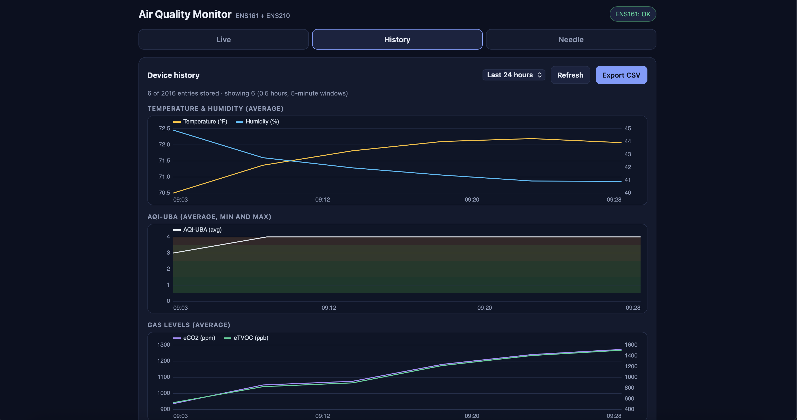
The same charts, but built from the on-device 5-minute history instead of the live buffer, with a range selector (6 hours to 7 days) and CSV export.
Needle
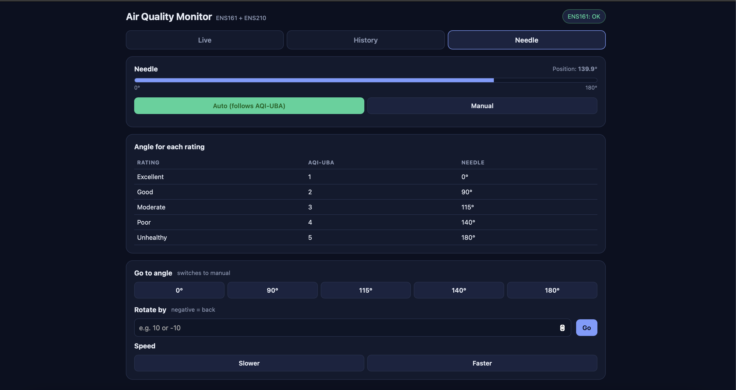
Manual control: an Auto/Manual toggle, a reference table of which AQI-UBA rating maps to which angle, one-tap "go to angle" buttons for each rating, a free-form rotate-by-degrees input, and motor speed adjustment.
Endpoints, for anyone scripting against it directly:
| Endpoint | Purpose |
|---|---|
GET /status | Current reading, needle state, and device status as JSON |
GET /history?n=N | The newest N history entries as compact JSON |
GET /rotate?degrees=X | Rotate the needle by X° (switches to Manual) |
GET /goto?degrees=X | Move the needle to an absolute angle (switches to Manual) |
GET /mode?auto=0|1 | Switch between Auto and Manual |
GET /speed?direction=faster|slower | Adjust stepper speed |
GET /brightness?pct=X | Set LED brightness, 0–100 |
Wire, WiFi, and WebServer ship with the ESP32 core.Code/OhareAir/OhareAir.ino and fill in your Wi-Fi credentials: const char* ssid = "";
const char* password = "";TEMP_OFFSET_C) tuned for this specific board; a different enclosure, a different MCU, or even just a different ambient environment can shift the true offset enough that eTVOC, eCO2, and AQI-UBA all read differently than they would with perfect compensation.| Qty | Value | Footprint | References |
|---|---|---|---|
| 11 | LOGO | LOGO | G***, G***, G***, G***, G***, G***, G***, G***, G***, G***, G*** |
| 4 | 10k | Resistor_SMD:R_0805_2012Metric_Pad1.20x1.40mm_HandSolder | R1, R2, R4, R5 |
| 4 | Conn_01x01_Pin | Connector_PinHeader_1.27mm:PinHeader_1x01_P1.27mm_Vertical | 3V1, 5V1, G1, Gd1 |
| 3 | 10uF | Capacitor_SMD:C_0805_2012Metric_Pad1.18x1.45mm_HandSolder | C2, C5, C6 |
| 3 | MountingHole | MountingHole:MountingHole_3.2mm_M3 | H1, H2, H3 |
| 2 | 0.1uF | Capacitor_SMD:C_0805_2012Metric_Pad1.18x1.45mm_HandSolder | C3, C4 |
| 2 | Conn_02x22_Odd_Even | Connector_PinHeader_2.54mm:PinHeader_2x22_P2.54mm_Vertical | J9, J10 |
| 1 | .1uF | Capacitor_SMD:C_0805_2012Metric_Pad1.18x1.45mm_HandSolder | C1 |
| 1 | 470 | Resistor_SMD:R_0805_2012Metric_Pad1.20x1.40mm_HandSolder | R3 |
| 1 | BSS138 | BSS138:SOT-23_3L_ONS-L | Q1 |
| 1 | Conn_01x03_Socket | Connector_PinHeader_1.27mm:PinHeader_1x03_P1.27mm_Vertical | J1 |
| 1 | ENS161-BLGT | ENS161:XDCR_ENS161-BLGT | U1 |
| 1 | ENS210-LQFM | ENS210:SON-04-ENS210_2X2_AMS-L | U2 |
| 1 | IN-PI15TAT5R5G5B | IN-PI15TAT5R5G5B:IN-PI15_INL | LED1 |
| 1 | MCP1700T-1802E/TT | MCP1700T:SOT-23_MC_MCH-L | U3 |
| 1 | TestPoint_Small | TestPoint:TestPoint_Pad_1.0x1.0mm | TP1 |
| 1 | VAL** | mouse-bite:mouse-bite-3mm-6mm | mouse-bite-3mm-6mm |
It measures 87.2 × 69 mm and has 2 copper layers, 1.6 mm thick.
39 parts, built around the ENS161-BLGT, ENS210-LQFM, MCP1700T-1802E/TT(MS) and BSS138. The full list of its parts is on this page, with links to each part's symbol and footprint where PCBKit's library has them.
From the Will946/O-hareAir repository on GitHub, at the commit this page was made from: the board is OhareV1PCB/OhareV1.kicad_pcb and its schematic OhareV1PCB/OhareV1.kicad_sch. PCBKit opens the board in the browser, with nothing to install.
Its repository publishes it under the MIT licence: you may reuse it on that licence's terms (keep the author's notice, and for a copyleft licence share your changes alike).


StuckAtPrototype/Racer
These are structured into their own files. I could have used submodules, but decided against it.

StuckAtPrototype/AirCube
Works standalone out of the box. Pairs with Home Assistant in minutes. Other platforms are supported through community-contributed extensions.


StuckAtPrototype/PCB_business_card_remake
A custom PCB based "business" card that lets you play a version of Flappy Bird.

cubistmind/__pCennnBeist
A custom PCB based "emniii😞😞" card that lets you play a version of Flappy Bird

mjvarga/Interactive-Glowpad-PCB-Design
A 5-pad capacitive touch board built around the ESP32-S3, featuring addressable RGB LEDs and piezo audio feedback.