4 layers43.2 × 43.2 mm
Qwiic GPS RTK SMA - ublox ZED F9P
Zmotive/HY_550CJ_Control_board
This Project is still under development and not all features have been tested. As I work through the hardware I will continue to update.
143 parts

 Will946/GNSS
u-blox ZED-F9P RTK GNSS breakout board with dual-band L1/L2 reception and centimeter-level positioning accuracy.
ZED F9P is an open-source printed circuit board by Will946, from the Will946/GNSS repository on GitHub, published under the MIT licence. It is a 4-layer board of 52 × 57.8 mm with 65 parts on 51 nets, routed with 416 tracks and 208 vias.
It is built around the ZED-F9P-04B and PRTR5V0U2F. Its parts include 25 resistors, 8 connectors, 7 capacitors, 6 diodes and 2 ICs. It belongs with the radio and wireless boards of this library.


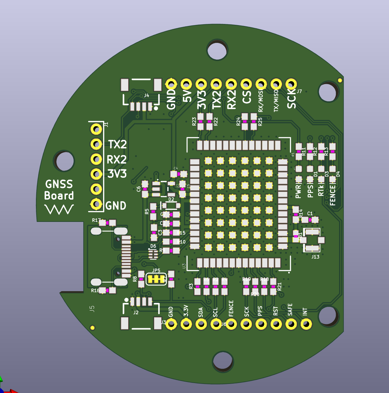
Board for an autonomous cart that follows the edge of a lawn and sprays weed killer along the border. Goal is centimeter level positioning using RTK corrections so the cart can hold a precise line along a mapped boundary. Prototyping this board is the only part of the project built so far.
Not currently in use on the cart. Prototyping this board cost way more than expected, and the rest of the cart, drive base, sprayer, controller, was never built as a result. Right now this is just the GNSS board sitting on its own.
The ZED-F9P decodes both L1 and L2 bands at the same time, which speeds up how fast it locks a fixed RTK solution and helps under partial sky obstruction, useful near fences, trees, or the edge of a house. With a clear view of sky and a valid RTCM3 correction stream, this board is capable of about 10 mm 3D accuracy.
Two things it needs to actually hit that accuracy:
| Interface | Description |
|---|---|
| USB-C | Enumerates as a standard COM port, carries power and full UBX/NMEA data |
| UART1 | 3.3V TTL, general purpose NMEA/UBX I/O |
| UART2 | 3.3V TTL, dedicated to RTCM3 correction data. Input on a rover, output on a base |
| I2C DDC | u-blox's I2C implementation, shares physical pins with SPI |
| SPI | Alternate to I2C on the same pins, must be explicitly selected |
Interface select jumper: I2C and SPI share pins, so only one is active at a time.
Set this before wiring your host MCU. An unexpected jumper state is the most common reason I2C or SPI fails to come up.
| Item | Detail |
|---|---|
| GNSS module | u-blox ZED-F9P |
| Antenna connector | U.FL, active antenna with bias tee power |
| Antenna requirement | L1/L2 dual band active GNSS antenna |
| Logic level | 3.3V |
| Backup power | Rechargeable cell, retains config/almanac about 2 weeks unpowered |
| Board interconnect | 0.1" breadboard compatible headers |
| Input power | 5V or 3.3V |
| Pin | Function | Notes |
|---|---|---|
| 5V / 3V3 | Power in | Select per your supply |
| GND | Ground | |
| TX1 / RX1 | UART1, NMEA/UBX | 3.3V TTL, general data |
| TX2 / RX2 | UART2, RTCM3 | 3.3V TTL, correction data in/out |
| SDA / SCL | I2C, DDC | Shares pins with SPI, see jumper |
| MISO / MOSI / SCK / CS | SPI | Enabled only when jumper closed |
| PPS | Pulse per second | Precision timing output |
| SAFEBOOT | Firmware recovery | Pull low during boot to enter recovery |
As a rover on the cart:
If running your own base station instead of NTRIP:
Correction delivery options:
| Qty | Value | Footprint | References |
|---|---|---|---|
| 12 | 33 | 0603 | R2, R3, R4, R6, R18, R19, R20, R21, R22, R23, R24, R25 |
| 5 | 1k | 0603 | R1, R5, R11, R12, R13 |
| 4 | 1.0uF | 0603 | C2, C3, C4, C6 |
| 4 | FIDUCIALUFIDUCIAL | MICRO-FIDUCIAL | JP21, JP61, JP71, JP81 |
| 4 | STAND-OFF | STAND-OFF | JP31, JP41, JP91, JP101 |
| 3 | SMT-JUMPER_2_NC_TRACE_SILK | JP1, JP2, JP3 | |
| 2 | 0.1uF | 0603 | C5, C7 |
| 2 | 2.2k | 0603 | R7, R8 |
| 2 | 27 | 0603 | R9, R10 |
| 2 | 5.1k | 0603 | R16, R17 |
| 2 | Qwiic Right Angle | 1X04_1MM_RA | J2, J4 |
| 1 | SMT-JUMPER_2_NO_SILK | JP4 | |
| 1 | 1X06_NO_SILK | J6 | |
| 1 | 1X09_NO_SILK | J7 | |
| 1 | SMT-JUMPER_3_2-NC_TRACE_SILK | JP5 | |
| 1 | USB-C-16P | J5 | |
| 1 | |||
| 1 | 0.5A/40V/420mV | SOD-323 | D2 |
| 1 | 10 | 0603 | R14 |
| 1 | 100k | 0603 | R15 |
| 1 | 3.3V | SOT23-5 | U2 |
| 1 | 47pF | 0603 | C1 |
| 1 | BLUE | LED-0603 | D4 |
| 1 | FERRITE_BEAD-120_OHM-0402 | 0402 | FB1 |
| 1 | FRAME-LETTER | CREATIVE_COMMONS | FRAME1 |
| 1 | GREEN | LED-0603 | D3 |
| 1 | LOGO | LOGO | G*** |
| 1 | PRTR5V0U2F | SOT886 | D6 |
| 1 | PTH | 1X04_NO_SILK | J3 |
| 1 | RED | LED-0603 | LED2 |
| 1 | Radio | 1X06_NO_SILK | J1 |
| 1 | U.FL | U.FL | J13 |
| 1 | Yellow | LED-0603 | D1 |
| 1 | ZED-F9P | ZED-F9P | U3 |
It measures 52 × 57.8 mm and has 4 copper layers, 1.6 mm thick.
65 parts, built around the ZED-F9P-04B and PRTR5V0U2F. The full list of its parts is on this page, with links to each part's symbol and footprint where PCBKit's library has them.
From the Will946/GNSS repository on GitHub, at the commit this page was made from: the board is GNSSPCB/ZED-F9P.kicad_pcb and its schematic GNSSPCB/ZED-F9P.kicad_sch. PCBKit opens the board in the browser, with nothing to install.
Its repository publishes it under the MIT licence: you may reuse it on that licence's terms (keep the author's notice, and for a copyleft licence share your changes alike).
Zmotive/HY_550CJ_Control_board
This Project is still under development and not all features have been tested. As I work through the hardware I will continue to update.

takuhoTech/CelestNavi-Combo
Ready-to-use GNSS+CLAS receiver with integrated loop antenna

averywallis/Feather-ZED-F9P-GPS
KiCad files for a ZED-F9P GPS Featherwing


jirayu3141/F9P_moving_base_pcb
2 ZED F9P as moving base and rovers

Poppy-Robotics/rtk
CAN enabled, RTK GNSS module for robotics based on u-blox ZED-X20P


chenzhuoyu/rainbow-board
ECP5 FPGA breakout board for Colorlight i5 / i9