2 layers44.5 × 61 mm
 wileycousins/clockblock2
minimalistic LED clock in a block
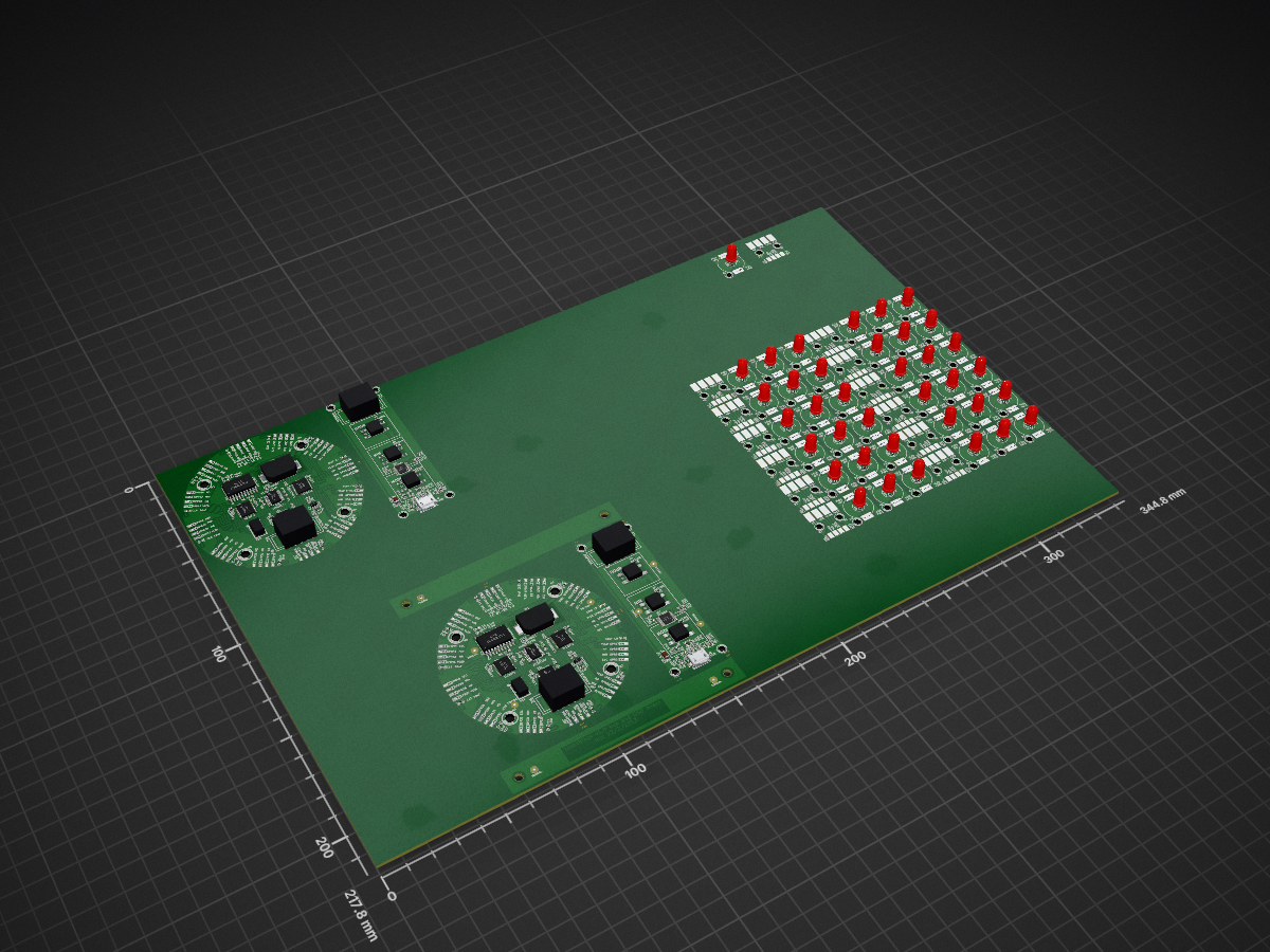
Clockblock pcb is an open-source printed circuit board by wileycousins, from the wileycousins/clockblock repository on GitHub. It is a 2-layer board of 344.8 × 217.8 mm with 604 parts on 87 nets, routed with 3,723 tracks and 384 vias.
It is built around the ATTINY167-MU, TLC5971PWP and FT230XQ-R, with the PCF2129AT/2 among its other parts. Its parts include 54 capacitors, 45 diodes, 26 resistors, 14 ICs and 8 connectors. It belongs with the lEDs and displays boards and the AVR (ATmega, ATtiny) boards of this library.


An LED clock in a block of wood. This repository contains the electronics design files and firmware source code.
Firmware is written in C++ and compiled in GCC 4.6.2 with AVR modifications. If you're using a Mac, install CrossPack for AVR 2013-02-12 for all the necessary tools. Otherwise, do some Googling.
The clockblock uses an ATTiny167 with 16KB of flash and 512B of RAM. At compilation, the application takes about 6KB of program and 30B of RAM. Currently firmware must be flashed onto the board with an ISP, but hardware supports USB bootloading*. An Arduino-compatible bootloader is in the works.
*v1.0 hardware has a trace that must be cut and replaced with a capacitor for this to work. See issue #6.
The PCBs are designed in KiCad. There are gerber files in the repo, but your best bet is to generate them yourself from KiCad. Components are from these libraries, but you shouldn't have to install them to view the schematic and board files if you don't want to.
The boards are almost entirely surface mount, so solder-paste and a reflow tool of some sort (hot-air gun, toaster, hot-plate) are recommended. If anyone manages this with just an iron, I'd love to see pictures, because that's awesome. Shameless self promotion: I know about this pretty good toaster oven control board for solder reflow.
| Qty | Value | Footprint | References |
|---|---|---|---|
| 100 | M2 | M2, M2, M2, M2, M2, M2, M2, M2, M2, M2, M2, M2, M2, M2, M2, M2 +84 | |
| 50 | VLED | 3x5MM_SM-PAD | PAD1, PAD1, PAD1, PAD1, PAD1, PAD1, PAD1, PAD1, PAD1, PAD1, PAD1, PAD1, PAD1, PAD5, PAD5, PAD5 +34 |
| 37 | LED | LED-5mm | LED1, LED1, LED1, LED1, LED1, LED1, LED1, LED1, LED1, LED1, LED1, LED1, LED1, LED1, LED1, LED1 +21 |
| 37 | OUT | 3x5MM_SM-PAD | PAD6, PAD6, PAD6, PAD6, PAD6, PAD6, PAD6, PAD6, PAD6, PAD6, PAD6, PAD6, PAD6, PAD6, PAD6, PAD6 +21 |
| 36 | VAL** | MOUSEBITE | MOUSEBITE, MOUSEBITE, MOUSEBITE, MOUSEBITE, MOUSEBITE, MOUSEBITE, MOUSEBITE, MOUSEBITE, MOUSEBITE, MOUSEBITE, MOUSEBITE, MOUSEBITE, MOUSEBITE, MOUSEBITE, MOUSEBITE, MOUSEBITE +20 |
| 26 | 10uF | 0603(1608m) | C4, C4, C10, C10, C11, C11, C12, C12, C13, C13, C14, C14, C15, C15, C21, C21 +10 |
| 24 | HR | TE_1551573-5_SPRING-FINGER | SPR2, SPR2, SPR10, SPR10, SPR14, SPR14, SPR18, SPR18, SPR22, SPR22, SPR26, SPR26, SPR30, SPR30, SPR34, SPR34 +8 |
| 24 | MIN | TE_1551573-5_SPRING-FINGER | SPR3, SPR3, SPR11, SPR11, SPR15, SPR15, SPR19, SPR19, SPR23, SPR23, SPR27, SPR27, SPR31, SPR31, SPR35, SPR35 +8 |
| 24 | SEC | TE_1551573-5_SPRING-FINGER | SPR4, SPR4, SPR12, SPR12, SPR16, SPR16, SPR20, SPR20, SPR24, SPR24, SPR28, SPR28, SPR32, SPR32, SPR36, SPR36 +8 |
| 24 | VLED | TE_1551573-5_SPRING-FINGER | SPR1, SPR1, SPR13, SPR13, SPR17, SPR17, SPR21, SPR21, SPR25, SPR25, SPR29, SPR29, SPR33, SPR33, SPR37, SPR37 +8 |
| 13 | HOUR | 3x5MM_SM-PAD | PAD2, PAD2, PAD2, PAD2, PAD2, PAD2, PAD2, PAD2, PAD2, PAD2, PAD2, PAD2, PAD2 |
| 13 | HOUR | 2x3MM_SM-PAD | LND2, LND2, LND2, LND2, LND2, LND2, LND2, LND2, LND2, LND2, LND2, LND2, LND2 |
| 13 | MIN | 3x5MM_SM-PAD | PAD3, PAD3, PAD3, PAD3, PAD3, PAD3, PAD3, PAD3, PAD3, PAD3, PAD3, PAD3, PAD3 |
| 13 | MIN | 2x3MM_SM-PAD | LND3, LND3, LND3, LND3, LND3, LND3, LND3, LND3, LND3, LND3, LND3, LND3, LND3 |
| 13 | SEC | 3x5MM_SM-PAD | PAD4, PAD4, PAD4, PAD4, PAD4, PAD4, PAD4, PAD4, PAD4, PAD4, PAD4, PAD4, PAD4 |
| 13 | SEC | 2x3MM_SM-PAD | LND4, LND4, LND4, LND4, LND4, LND4, LND4, LND4, LND4, LND4, LND4, LND4, LND4 |
| 13 | VLED | 2x3MM_SM-PAD | LND1, LND1, LND1, LND1, LND1, LND1, LND1, LND1, LND1, LND1, LND1, LND1, LND1 |
| 12 | 0.1uF | 0603(1608m) | C16, C16, C17, C17, C18, C18, C24, C24, C26, C26, C27, C27 |
| 10 | 1uF | 0603(1608m) | C1, C1, C2, C2, C3, C3, C19, C19, C20, C20 |
| 9 | VAL** | FIDUCIAL | FIDUCIAL, FIDUCIAL, FIDUCIAL, FIDUCIAL, FIDUCIAL, FIDUCIAL, FIDUCIAL, FIDUCIAL, FIDUCIAL |
| 8 | MOUSEBITE | , , , , , , , | |
| 8 | M3 | M3, M3, M3, M3, M3, M3, M3, M3 | |
| 8 | 1kΩ | 0603(1608m) | R10, R10, R11, R11, R12, R12, R13, R13 |
| 8 | VAL** | M2 | M2, M2, M2, M2, M2, M2, M2, M2 |
| 8 | opt10kΩ | 0603(1608m) | R4, R4, R5, R5, R6, R6, R7, R7 |
| 6 | 1.1kΩ±1% | 0603(1608m) | R1, R1, R2, R2, R3, R3 |
| 6 | TLC5971 | HTSSOP20 | IC1, IC1, IC2, IC2, IC3, IC3 |
| 4 | 27Ω | 0603(1608m) | R8, R8, R9, R9 |
| 4 | 47pF | 0603(1608m) | C22, C22, C23, C23 |
| 4 | VAL** | 0.125in_NPTH | 0.125in_NPTH, 0.125in_NPTH, 0.125in_NPTH, 0.125in_NPTH |
| 2 | 3A | 0603(1608m) | FB1, FB1 |
| 2 | 3V-COINCELL | LINX_BAT-HLD-012-SMT | BT1, BT1 |
| 2 | 4.7uF | 1206(3216m)_tant-cap | C25, C25 |
| 2 | ATTINY167 | TSSOP20 | IC6, IC6 |
| 2 | AVR_ISP | 2x3-array | P14, P14 |
| 2 | FT230X | SSOP16 | IC7, IC7 |
| 2 | HEART | 0603(1608m)_led | LED2, LED2 |
| 2 | HOUR | SPST_6MM_sm | S1, S1 |
| 2 | MAINtoUSB | 2x5-PIN-ARRAY_P100MIL_sm | P15, P15 |
| 2 | MIN | SPST_6MM_sm | S2, S2 |
| 2 | MODE | SPST_6MM_sm | S3, S3 |
| 2 | PCF2129AT | SOIC20 | IC4, IC4 |
| 2 | PWR | 0603(1608m)_led | LED5, LED5 |
| 2 | RX | 0603(1608m)_led | LED4, LED4 |
| 2 | TLV71333 | SOT23-5 | IC5, IC5 |
| 2 | TX | 0603(1608m)_led | LED3, LED3 |
| 2 | USB | MICROUSB_sm | J2, J2 |
| 2 | USBtoMAIN | 2x5-PIN-ARRAY_P100MIL_sm | P13, P13 |
It measures 344.8 × 217.8 mm and has 2 copper layers, 1.6 mm thick.
604 parts, built around the ATTINY167-MU, TLC5971PWP, FT230XQ-R and PCF2129AT/2. The full list of its parts is on this page, with links to each part's symbol and footprint where PCBKit's library has them.
From the wileycousins/clockblock repository on GitHub, at the commit this page was made from: the board is pcb/clockblock-pcb.kicad_pcb. PCBKit opens the board in the browser, with nothing to install.
Its repository states no licence, so its author keeps all rights: ask wileycousins before reusing the design.

74hc595/Numitron-Clock
An alarm clock using 9-segment numitron displays


BerkeleyLab/DxP-data-logger
Hardware design for the DxP (Distributed sensor Profiling) data logger that connects to a DxP sensor probe.

mirra-org/mirra
Firmware, web app/server and documentation for the MIRRA project.

brooklynresearch/FerrousControl
Ferrofluid controlled through an electromagnetic array

s-light/LED_Board_PCB
small round PCB with TI TLC5971 12ch 16bit LED-driver and NICHIA NSSM124AT RGB-LED. (original for Lumifluidus Prototyp)

s-light/LEDBoard_1x4_16bit_highdensity
LEDBoard 1x4 High Density - with TLC5971 16Bit LED-Driver