

2 layers82 × 120 mm
Sample Numeric Keyboard
famichu/MagLev_Switch_MX
The 3D printable magnetic levitation contactless switch with the linear output hall effect sensor.
66 parts467

Creating a replacement for a broken Villeroy & Boch whirlpool remote
Remote is an open-source printed circuit board by wilcotomassen, from the wilcotomassen/whisperpool-remote repository on GitHub. It is a 2-layer board of 40 × 70 mm with 17 parts on 13 nets, routed with 170 tracks and 13 vias.
It is built around the ATMEGA328-AU. Its parts include 2 capacitors, 2 resistors, 2 diodes, 1 IC and 1 connector. It belongs with the AVR (ATmega, ATtiny) boards of this library.
TLDR: Whirlpool remote didn't work. I replaced it with an Arduino based remote that sent out the same RC5 remote commands using this Arduino IR-Remote library.
You can find the code here and the schematics and pcb design here
I think this same solution should work for following whirlpools from Villeroy & Boch:
- Whisper Airpool
- Clairpool
- Whisper Whirlpool
- Whisper Combipool
Our home has a Villeroy and Boch whirlpool installed and after about half a year after we moved in and about three uses, the remote stopped functioning.
Opening the battery compartment made the cause cleary very quickly. The batteries started leaking and (probably) deposited their acidic schmoo all over the pcb, corriding it and the components. As the remote enclosure is water proof and seems to be glued together, there was no easy way to clean it. After trying to rinse it out with some household chemicals through the battery compartment, it still didn't work.
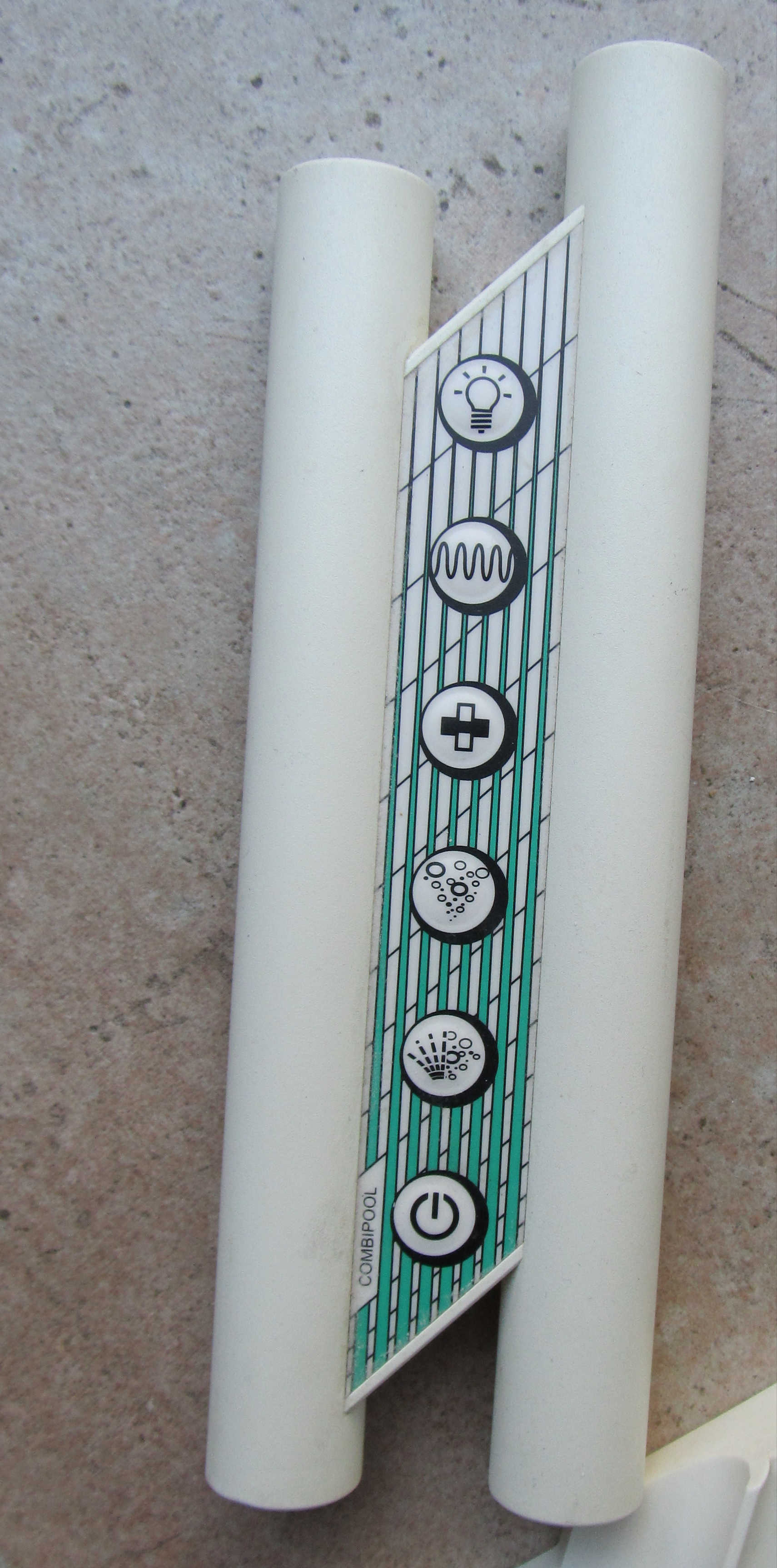
There are replacement remotes availble, but they are about 150 euros. I like a working whirlpool, but not that much. So I decided to tear it down and see if there was a likely fix.
There was no easy way to open the remote enclosure (because it's water proof), so I ended up cracking it open with pliers to get to in. Inside there's pretty much what one would expect, a tube to act as the battery compartment, a small PCB in the middle doing the logic and an IR led to send the commands.
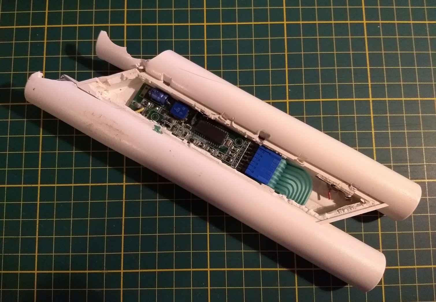
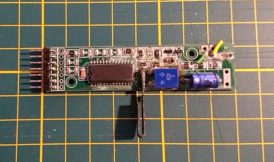
As you can see there's quite a bit of corrosion on the PCB, either from moisture or from battery acid. Cleaning it with some isopropyl alcohol might salvage this, but I opted to toss it, rather that attempt that. The cut leads are from the IR led.
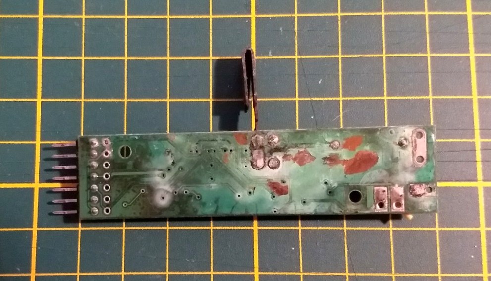
The main attraction on the PCB is the Philips/NXP IC, which is an RC5 Infrared remote control transmitter that does pretty much everything on the board.
These markings are printet on the chip, next to the Philips logo:
SAA3010T
79030C
US0211 2 Y
The data sheet can be found here
The chip handles the scanning of the remote buttons, and converting those into valid RC5 protocol commands and sending them out into the world via the IR led.
The datasheet explains how the key scan combinations are converted into the RC5 address and command bits, so there's no code that runs on the IC for this specific remote; all the information for the commands is in the connections on the PCB (which is good, because I cannot capture the RC commands from a non-working remote).
A command in the RC5 protocol is composed of
more information here
We need to figure out the address and command bits to make a working remote.
Finding the correct address bits was as simple as finding which Z- and
DR lines from the IC were connected on the PCB. They turned out to be
Z3 (pin 6) and DR7 (pin 9). From the System matrix in the datasheet on
page 10, this dermines the system number 31 (a reserved system number),
which has these system bits: 11111.
With a multimeter I checked how the buttons wires corresponded to the pins on the RC5 IC. It turns out that one wire was connected to the X5 pin and all the other pins to 6 DR-lines.
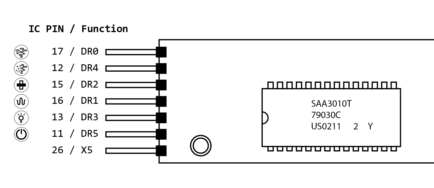
When a buttons is pressed, it connects on of the DR pins to the X5 pin. The datasheet contains a nice table on page 9 to lookup the command bits for those X/DR combinations.
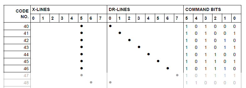
| Button | Code | Start bit | Field bit | Control bit | Address bits | Command bits | => | Complete command |
|---|---|---|---|---|---|---|---|---|
 | 40 | 1 | 1 | 1/0 | 11111 | 101000 | => | 11111111101000 |
 | 41 | 1 | 1 | 1/0 | 11111 | 101001 | => | 11111111101001 |
 | 42 | 1 | 1 | 1/0 | 11111 | 101010 | => | 11111111101010 |
 | 43 | 1 | 1 | 1/0 | 11111 | 101011 | => | 11111111101011 |
 | 44 | 1 | 1 | 1/0 | 11111 | 101100 | => | 11111111101100 |
 | 45 | 1 | 1 | 1/0 | 11111 | 101101 | => | 11111111101101 |
Once the protocol was found, it was fairly easy to find an Arduino library that was able to send out RC5 commands: Arduino IR-Remote
| Qty | Value | Footprint | References |
|---|---|---|---|
| 4 | MountingHole | MountingHole:MountingHole_3.2mm_M3 | H1, H2, H3, H4 |
| 2 | R_Small | Resistor_SMD:R_0805_2012Metric_Pad1.15x1.40mm_HandSolder | R1, R2 |
| 2 | SW_Push | Button_Switch_SMD:SW_SPST_B3S-1000 | MODE, ON/OFF |
| 1 | ATMEGA328-AU | Package_QFP:TQFP-32_7x7mm_P0.8mm | U1 |
| 1 | AVR-ISP-6 | Connector_PinHeader_2.54mm:PinHeader_2x03_P2.54mm_Vertical | J1 |
| 1 | Battery_Cell | Battery:BatteryHolder_Keystone_107_1x23mm | BT1 |
| 1 | CP_Small | Capacitor_SMD:CP_Elec_6.3x4.5 | C2 |
| 1 | C_Small | Capacitor_SMD:C_0805_2012Metric_Pad1.15x1.40mm_HandSolder | C1 |
| 1 | LED | LED_THT:LED_D5.0mm_Horizontal_O1.27mm_Z3.0mm_IRBlack | D1 |
| 1 | LED | LED_SMD:LED_0805_2012Metric_Pad1.15x1.40mm_HandSolder | D2 |
| 1 | Resonator_Small | Crystal:Resonator_SMD-3Pin_7.2x3.0mm_HandSoldering | Y1 |
| 1 | SW_SPDT | Button_Switch_SMD:SW_SPDT_PCM12 | SW1 |
It measures 40 × 70 mm and has 2 copper layers, 1.6 mm thick.
17 parts, built around the ATMEGA328-AU. The full list of its parts is on this page, with links to each part's symbol and footprint where PCBKit's library has them.
From the wilcotomassen/whisperpool-remote repository on GitHub, at the commit this page was made from: the board is hardware/remote.kicad_pcb. PCBKit opens the board in the browser, with nothing to install.
Its repository states no licence, so its author keeps all rights: ask wilcotomassen before reusing the design.
famichu/MagLev_Switch_MX
The 3D printable magnetic levitation contactless switch with the linear output hall effect sensor.

dqydj/PaperBack_EPaper_Display
Internet Connected or Standard Input EPaper Display

etimou/arduino-pro-mini-kicad
This is a clone of the well known arduino board "pro-mini" designed in kicad while the original was designed in eagle. Ref https://store.arduino.cc/arduino-pro-mini

andykarpov/karabas-pro
FPGA based retrocomputer with FDD and HDD controllers


