6 layers42.2 × 17.8 mm

 wickerwaka/PicoROM336
An RP2040-based ROM emulator
PicoROM-32 is an open-source printed circuit board by wickerwaka, from the wickerwaka/PicoROM repository on GitHub, published under the MIT licence. It is a 6-layer board of 40.8 × 17.6 mm with 67 parts on 101 nets, routed with 1,044 tracks and 121 vias.
It is built around the RP2040, 74LVC245ABQ and 74AHCT1G126GW, with the P25Q16SH-UXH-IR, NCP114AMX330TC and SN74LVC1G32DRYR(UMW) among its other parts. Its parts include 28 capacitors, 13 resistors, 11 ICs, 5 diodes and 5 connectors. It belongs with the RP2040 boards of this library.



PicoROM is an 8-bit ROM emulator in DIP-32 and DIP-28 form factors. Its primary use case is rapid iteration when experimenting with arcade hardware. PicoROM can emulate ROMs up to 2MBit (256KB) with access times of 70ns. Its compact size allows it to fit into almost any ROM socket regardless of how crowded the board might be.
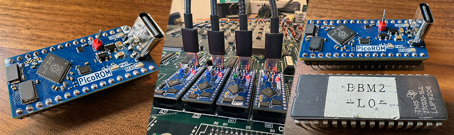
Features
Fully assembled versions are available from my store.
There are three hardware versions of PicoROM:
The abbreviated names POG, P28, and P32 identify which firmware image to use for each device.
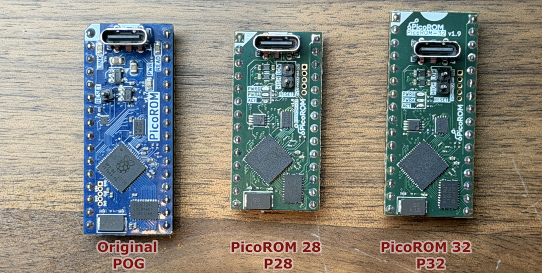
Version 2.0 introduced a custom USB protocol, replacing the emulated USB serial port used in version 1.x. The 2.0+ firmware is not compatible with the 1.x picorom tool, and vice versa.
Read INSTALL.md for detailed installation instructions.
PicoROM is controlled via USB using the picorom command-line tool. The tool can list connected devices, rename them, set parameters, upload ROM data, and update firmware.
Each PicoROM has a name used to identify it in commands. Multiple devices can be connected simultaneously—arcade boards often use multiple ROMs to increase memory size or bus width. List connected devices with picorom list:
foo:~ $ picorom list
Available PicoROMs:
  E66138528361BB3  [/dev/cu.usbmodem101]
  E661385490CD014  [/dev/cu.usbmodem102]
By default, PicoROMs use a unique hardware ID from flash memory as their name. You can rename devices based on their function—for example, an arcade board with two CPU ROMs (one for the lower 8 bits, one for the upper) could use cpu_low and cpu_high. These names can then be referenced in makefiles or scripts.
To identify which physical device corresponds to a name, use picorom identify <name> to flash its activity LED.
Rename a device with picorom rename:
foo:~ $ picorom rename E66138528361BB3 cpu_low
Renamed 'E66138528361BB3' to 'cpu_low'
Most commands follow the pattern picorom <COMMAND> <NAME> <ARGUMENTS...> where <NAME> identifies the target device. The primary command is upload, which transfers a binary image to PicoROM:
foo:~ $ picorom upload cpu_low cpu_low.bin
Uploading ROM [################################################################] Done.
After upload, PicoROM immediately serves the data for any address requests. Uploaded data is stored in RAM and lost when power is removed. To persist data across power cycles, save it to flash memory using the -s flag during upload or the commit command afterward:
foo:~ $ picorom upload cpu_low cpu_low.bin -s
Uploading ROM [################################################################] Done.
Storing to Flash - Done.

foo:~ $ picorom commit cpu_low
Storing to Flash - Done.
PicoROM defaults to 2MBit mode. If you upload a smaller image, the remaining address space is undefined. To emulate smaller ROM sizes, specify the size during upload:
foo:~ $ picorom upload cpu_low cpu_low_1mbit.bin 1MBit
Uploading ROM [################################################################] Done.
You can also download the current ROM contents from a device:
foo:~ $ picorom download cpu_low backup.bin
Downloading ROM [##############################################################] Done.PicoROM has an external reset pin for controlling the host hardware's reset signal. The pin is a tri-state output: high (+5V), low (ground), or high-impedance (z). Use this in build scripts to reset a system after uploading a new ROM:
# picorom makefile target to trigger reset and upload ROM image
picorom: cpu_low.bin cpu_high.bin
    picorom reset cpu_low low
    picorom upload cpu_low cpu_low.bin
    picorom upload cpu_high cpu_high.bin
    picorom reset cpu_low z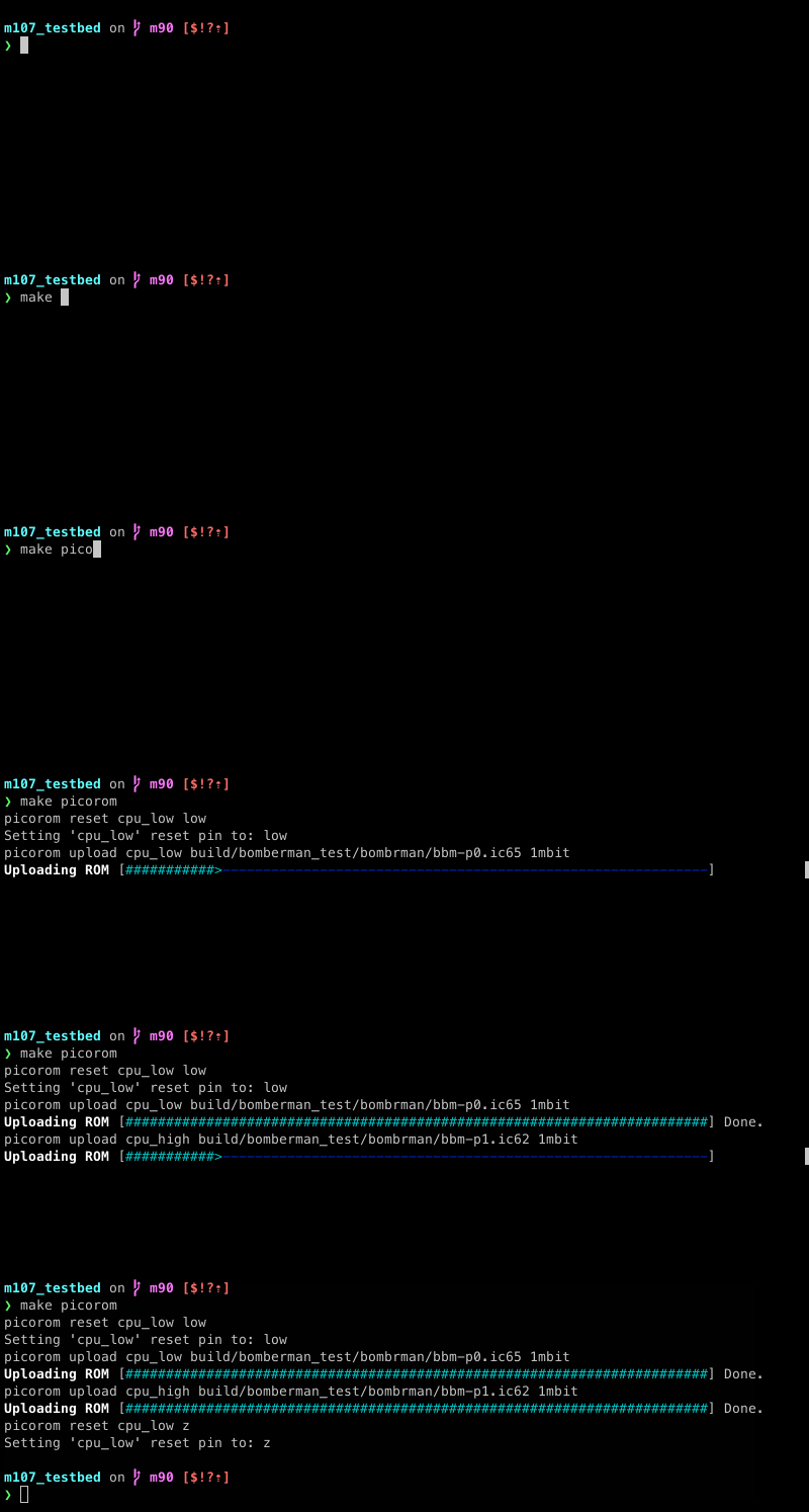
How you interface with each system's reset hardware will vary, and it may not always be possible to override the system's reset signal. The reset pin can also serve as a general-purpose controllable output.
PicoROM draws power from either USB-C or the 5V VCC input at pin 32/28, allowing it to function as a standalone ROM without a USB connection.
At startup, ROM data must be copied from flash to RAM, which takes approximately 8ms. ROM accesses are ignored until this completes. Additional delays may occur while the RP2040 waits for stable supply voltage. Systems with reset circuitry that delays startup for longer than 8ms should work reliably.
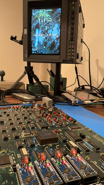 |
|---|
| Air Assault M107 running standalone with four PicoROMs |
The reset pin can mitigate startup timing issues. Set the initial_reset parameter to assert a reset value during the initial flash-to-RAM copy:
foo:~ $ picorom set cpu_low initial_reset high
initial_reset=highWorst-case access time is 70ns, measured from address assertion to data availability on the data bus. ROM datasheets typically call this "Address to Output Delay." Since PicoROM runs a synchronous instruction loop, access time varies depending on where in the loop the address is asserted.
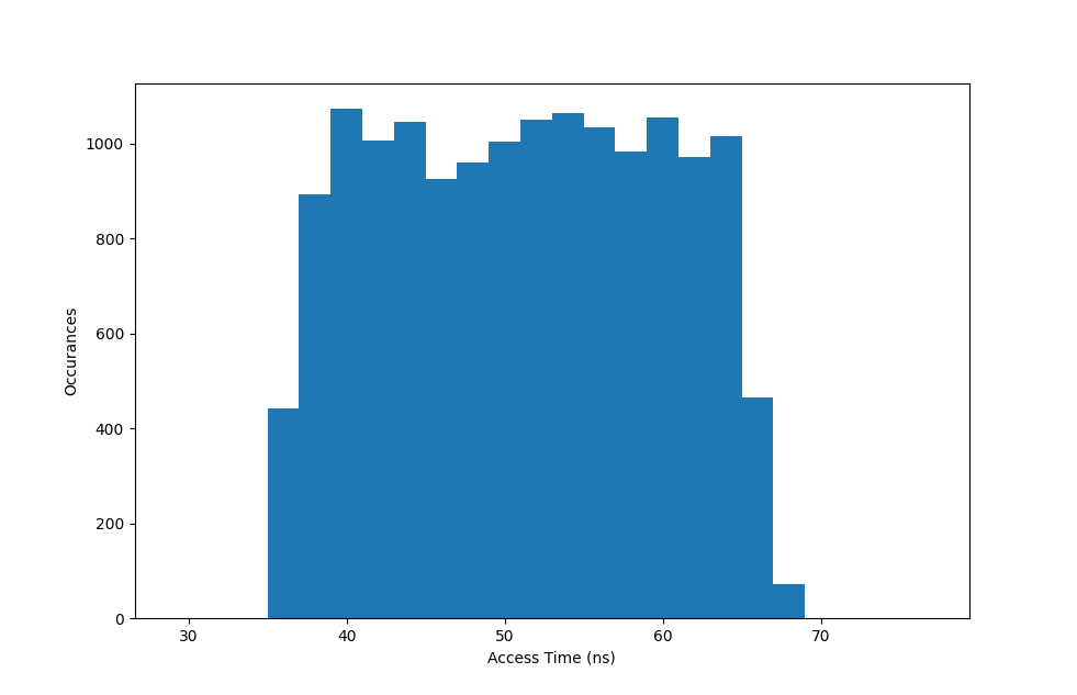
The delay from output/chip enable assertion to data bus active (Output Enable to Output Delay) is more consistent, with a worst case of 40ns. The inverse delay (enable deasserted to high-impedance) has not been measured but is assumed to be similar.
| Qty | Value | Footprint | References |
|---|---|---|---|
| 19 | 100n | Capacitor_SMD:C_0201_0603Metric | C5, C11, C12, C13, C14, C15, C16, C17, C18, C19, C20, C21, C22, C23, C24, C28 +3 |
| 9 | 1k | Resistor_SMD:R_0201_0603Metric | R1, R2, R5, R8, R9, R10, R11, R14, R29 |
| 7 | 1u | Capacitor_SMD:C_0402_1005Metric | C1, C4, C8, C10, C25, C26, C27 |
| 3 | 74LVC245 | PicoROM:V-QFN4525-20_L4.5-W2.5-P0.50-BL | U4, U5, U9 |
| 2 | 27 | Resistor_SMD:R_0201_0603Metric | R3, R4 |
| 2 | 27p | Capacitor_SMD:C_0402_1005Metric | C2, C3 |
| 2 | 5.1k | Resistor_SMD:R_0201_0603Metric | R6, R7 |
| 2 | 74AHCT1G126 | Package_TO_SOT_SMD:SOT-353_SC-70-5 | U11, U12 |
| 2 | Conn_01x16 | Connector_PinHeader_2.54mm:PinHeader_1x16_P2.54mm_Vertical | J3, J4 |
| 2 | LOGO | PicoROM:project_logo | G***, G*** |
| 2 | NCP114AMX330TCG | Package_DFN_QFN:OnSemi_XDFN4-1EP_1.0x1.0mm_EP0.52x0.52mm | U1, U8 |
| 2 | NSR0320MW2T1G | Diode_SMD:D_SOD-323 | D4, D5 |
| 1 | 74LVC1G32 | PicoROM:USON-6_L1.5-W1.0-P0.50-BL | U7 |
| 1 | 74LVC8245 | PicoROM:DHVQFN24_L5.5-W3.5-P0.50-BL-EP | U10 |
| 1 | ABM3-12.000MHZ-D2Y-T | Crystal:Crystal_SMD_5032-2Pin_5.0x3.2mm | Y1 |
| 1 | Conn_01x05_Pin | Connector_PinHeader_1.27mm:PinHeader_1x05_P1.27mm_Vertical | J5 |
| 1 | External Reset | Connector_PinHeader_2.54mm:PinHeader_1x02_P2.54mm_Vertical | J2 |
| 1 | Green | LED_SMD:LED_0402_1005Metric | D2 |
| 1 | LOGO | PicoROM:project_qrcode | G*** |
| 1 | LOGO | PicoROM:project_logo_large | G*** |
| 1 | RP2040 | PicoROM:RP2040-QFN-56 | U3 |
| 1 | Red | LED_SMD:LED_0402_1005Metric | D3 |
| 1 | USB_C_Receptacle_USB2.0 | Connector_USB:USB_C_Receptacle_G-Switch_GT-USB-7051x | J1 |
| 1 | W25Q16JVUXIQ | Package_SON:Winbond_USON-8-1EP_3x2mm_P0.5mm_EP0.2x1.6mm | U2 |
| 1 | Yellow | LED_SMD:LED_0402_1005Metric | D1 |

schenkmi/electronic-retro-computing-projects
In revision 2, the PCB size has been reduced by more than 50% and TAPuino support has been ditched. It now features a Micro SD slot and a few other improvements.


matthiasnowak/jewelled
This is a panel meant for production of the Earrings, allowing for 2 Earrings per panel.

garrettsworkshop/RAM128
128 kB Saturn 128k-compatible RAM expansion card for Apple II


DangerousPrototypes/BusPirate5-hardware
Bus Pirate Hardware and accessories for v5 and higher


It measures 40.8 × 17.6 mm and has 6 copper layers, 1.94 mm thick.
67 parts, built around the RP2040, 74LVC245ABQ, 74AHCT1G126GW and P25Q16SH-UXH-IR. The full list of its parts is on this page, with links to each part's symbol and footprint where PCBKit's library has them.
From the wickerwaka/PicoROM repository on GitHub, at the commit this page was made from: the board is hardware/PicoROM-32/PicoROM-32.kicad_pcb and its schematic hardware/PicoROM-28/PicoROM-28.kicad_sch. PCBKit opens the board in the browser, with nothing to install.
Its repository publishes it under the MIT licence: you may reuse it on that licence's terms (keep the author's notice, and for a copyleft licence share your changes alike).