
2 layers23 × 10 mm

 whowechina/sanwa_opt24
Optical sensor mod for Sanwa buttons (such as those in Pop'n Music, SDVX or IIDX)
Opt100umq is an open-source printed circuit board by whowechina, from the whowechina/sanwa_opt repository on GitHub, published under the CC0-1.0 licence. It is a 2-layer board of 67.3 × 17.8 mm with 14 parts on 7 nets, routed with 63 tracks and 1 via.
It is built around the ITR8402. Its parts include 3 resistors, 3 connectors, 2 ICs and 1 diode. It belongs with the sensors and measurement boards of this library.
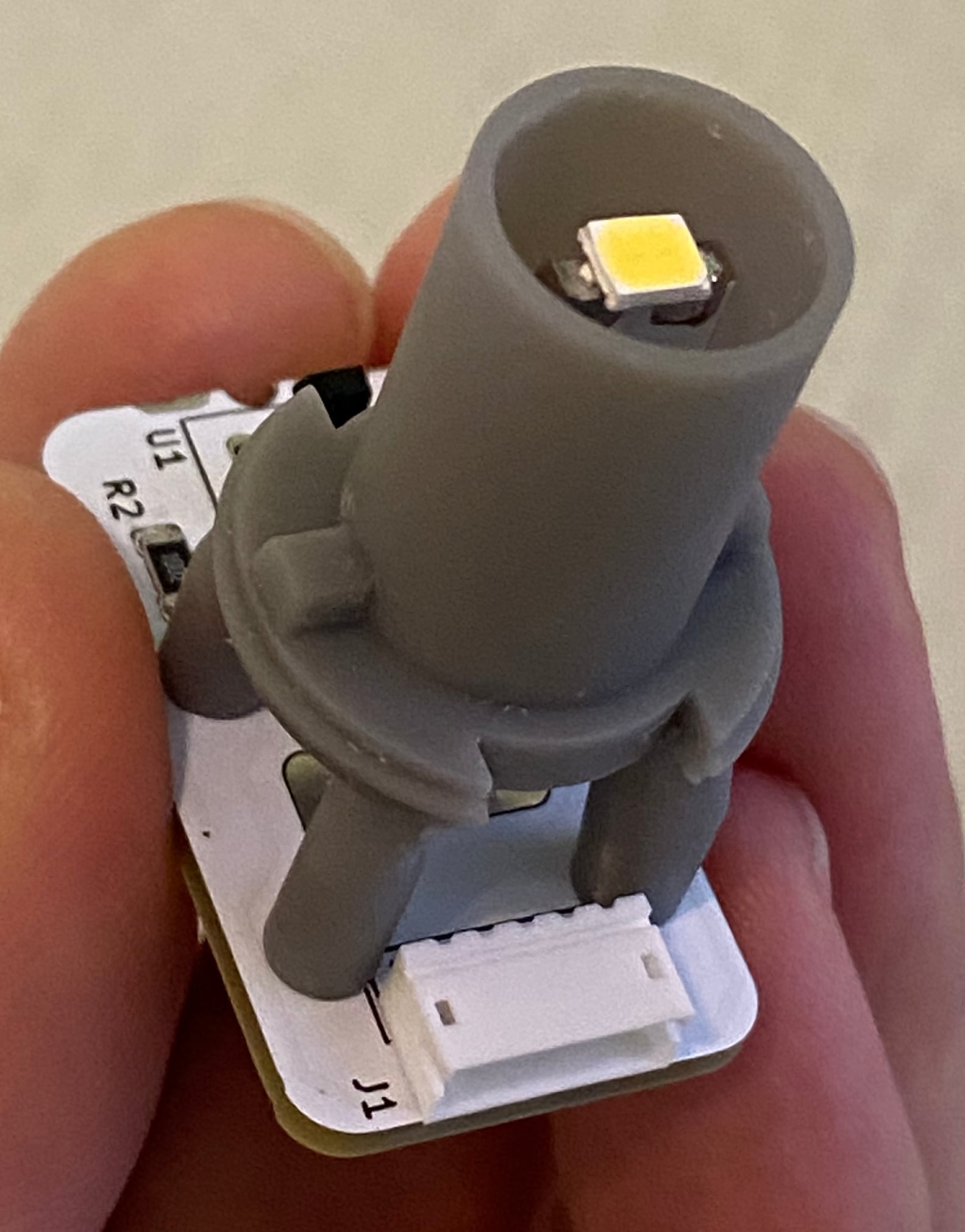
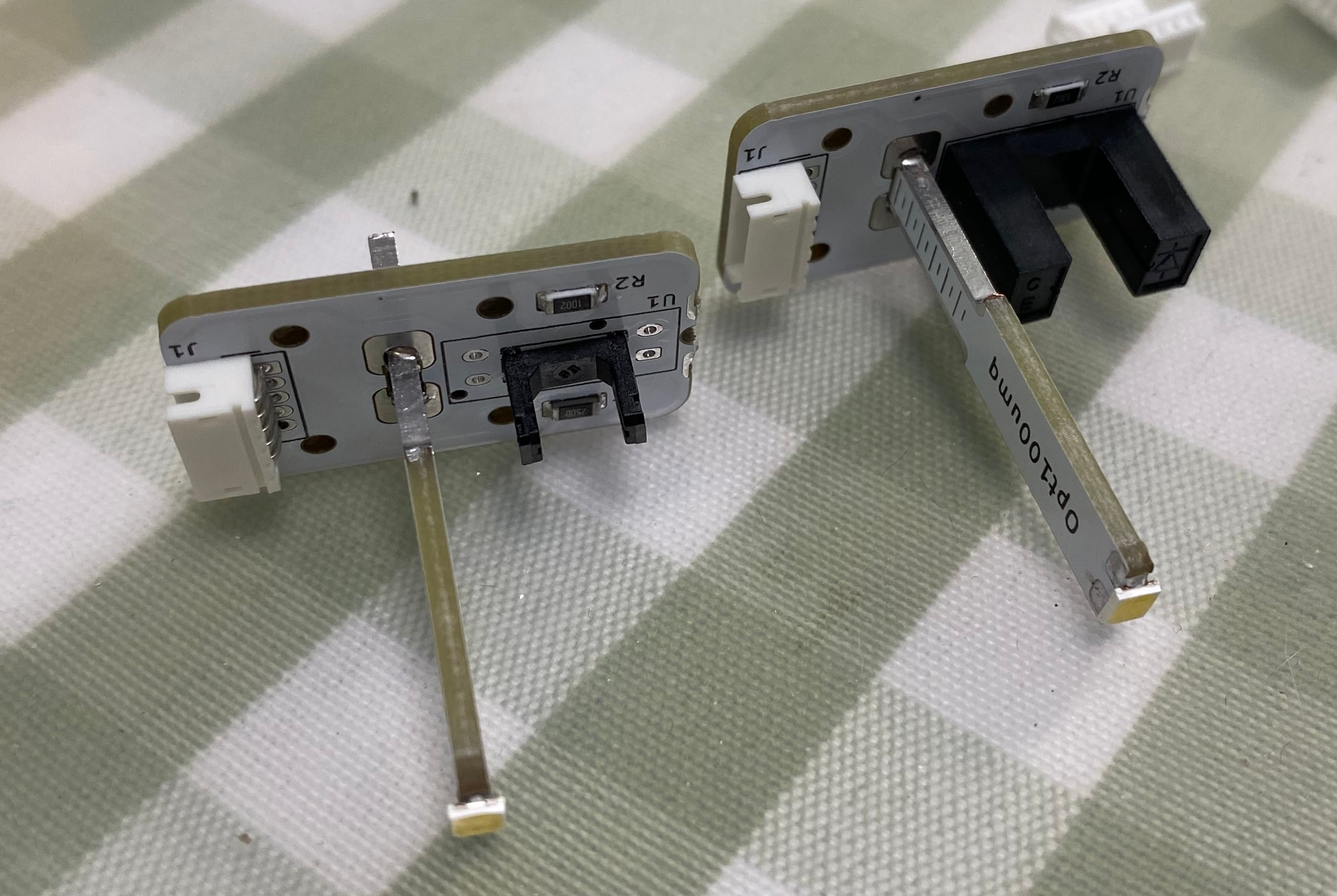
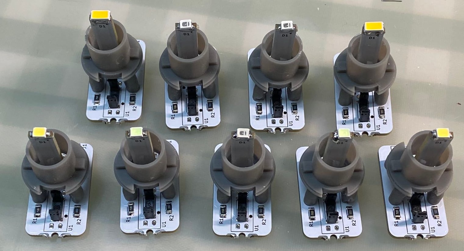
Traditional Sanwa buttons used in arcade use micro switches which wear out through time. This project creates a optical sensor module that can replace the whole original lamp/switch holder and the microswitch. It almost never wears out.
I build it originally for my Pop'n Music controller, the Sanwa OBSA-100UMP button. And it turned out Sanwa has its own standard and my design works for many other Sanwa buttons such as SDVX and IIDX.
The PCB contains the optical sensor part and the LED lamp part, you need to cut the lamp part from the main board.
For the optical sensor, the PCB supports both ITR1203 (inner pins) and discrete IR908-7C and PT908-7C pair (the outer pins). If you use discreate IR pairs, note that the IR emitter IR908-7C should be at the "U1" sign side, PT908-7C phototransistor should be at the opposite side.
Notes:
You need to print out the holder.stl. A resin printer is perfect for this. I'm not sure if an FDM printer with PLA has enough accuracy to do the work.
The interface to the mainboard is a ZHR-5, which is compatible with Sanwa's own buttons with optical sensors. I haven't made other types of interfaces yet. Maybe I will in the future.
| Qty | Value | Footprint | References |
|---|---|---|---|
| 5 | , , , , | ||
| 2 | 1K | Resistor_SMD:R_1206_3216Metric | R1, R3 |
| 1 | 4.7K | Resistor_SMD:R_1206_3216Metric | R2 |
| 1 | Conn_01x02 | opt100umq:SIDE_CONTACT_A | J2 |
| 1 | Conn_01x02 | opt100umq:SIDE_CONTACT_B | J3 |
| 1 | Conn_01x05 | opt100umq:ZHR-5 | J1 |
| 1 | IR26-21C_L110_TR8 | opt100umq:LED3528_SIDE | D1 |
| 1 | ITR1203 | opt100umq:ITR1203 | U1 |
| 1 | ITR8402 | opt100umq:ITR8402 | U2 |

google/mozc-devices
Circuit diagrams and firmware source code for Gboard DIY keyboards


hackclub/OnBoard
💡 Join 1,000 teenagers and make your first PCB with a $100 grant!


Twotoz/C5VRX
Ultra-minimal, zero-CPU 5.8 GHz analog FPV video receiver using ESP32-C5 Wi-Fi 6 PHY MODEM_DIAG, BitScrambler WBFM demodulation & resistor DAC CVBS

It measures 67.3 × 17.8 mm and has 2 copper layers, 1.6 mm thick.
14 parts, built around the ITR8402. The full list of its parts is on this page, with links to each part's symbol and footprint where PCBKit's library has them.
From the whowechina/sanwa_opt repository on GitHub, at the commit this page was made from: the board is opt100umq.kicad_pcb and its schematic opt100umq.kicad_sch. PCBKit opens the board in the browser, with nothing to install.
Its repository publishes it under the CC0-1.0 licence: you may reuse it on that licence's terms (keep the author's notice, and for a copyleft licence share your changes alike).