2 layers85 × 50 mm

 whowechina/arcade_pico13
Arcade switch replacement
Button is an open-source printed circuit board by whowechina, from the whowechina/arcade_pico repository on GitHub. It is a 2-layer board of 40 × 46 mm with 27 parts on 17 nets, routed with 201 tracks and 32 vias.
Its parts include 6 connectors, 6 switches, 4 resistors, 2 capacitors and 2 diodes. It belongs with the retro computing and games boards of this library.
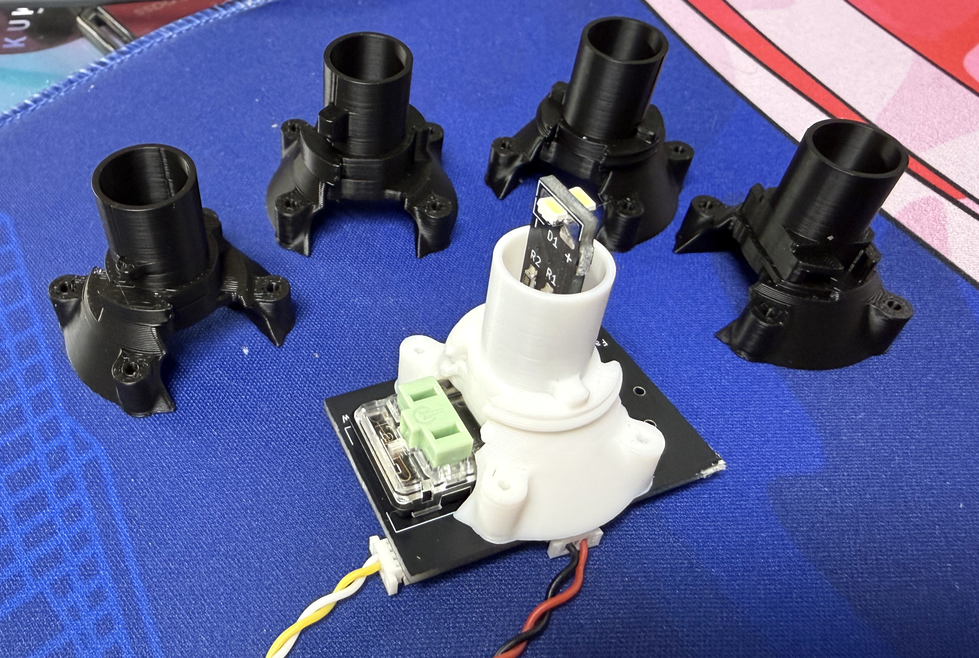
It's the successor to my sanwa_opt project. With it, you can use regular low-profile keyboard switches (or even optical sensors) on arcade buttons.
IO Board required);IO Board required);Thanks to many respectful guys/companies who made their tools or materials free or open source (KiCad, OnShape, InkScape, Raspberry things).
Special thanks to community projects and developers. And also these projects:
You can check out my other cool projects.


I made this project in my personal time with no financial benefit or sponsorship. I will continue to improve the project. I have done my best to ensure that everything is accurate and functional, there's always a chance that mistakes may occur. I cannot be held responsible for any loss of your time or money that may result from using this open source project. Thank you for your understanding.
It's CC-NC. So DIY for yourself and for your friend, don't make money from it. And plagiarism that doesn’t even dare to mention the original author is not acceptable. Please note that pooling orders and group buying for raw materials is acceptable.Selling any leftover components at cost (without profit) is also acceptable.
If you're interested in buying from me, or for commercial use, please contact me (Discord, QQ group, Goofish).
Main Board - The original controller board or IO board of your arcade system.Button Board - The PCB that contains the switch and LED daughter board. It's the major part of the Arcade Pico project.IO Board - The optional PCB that converts Hall effect switch signals to digital signals, and bridges regular LED signals to WS2812B RGB LED data signals. It's also part of the Arcade Pico project. It cannot replace your original Main Board.Lamp Holder - More accurately, it's a base equipped with both lamp and switch, but commonly referred to as lamp holder.IO BoardIt's the most common and easy case. The only thing you need to do is wiring the switch and LED signals from your Main Board to the corresponding connectors on the Button Board.
You can use mechanical switches or optical sensors, but you can't use magnetic switches or RGB lights.
Button Board → Button Input on Main BoardButton Board ← Lamp Output on Main BoardIO BoardWith magnetic switch, you can define your trigger and reset distance. With RGB light, you can define your button light color and effect. IO Board is required to drive the magnetic switch and RGB light.
Magnetic switch signals
Button Board → Hall In (SH1.0 3P) on IO BoardIO Board → Button Input on Main BoardRGB LED signals
Main Board → Lamp In (XH2.5 2P) on IO BoardIO Board → LED In (SH1.0 3P) on Button BoardButton Board → LED In (SH1.0 3P) on next Button Board (if any)Button Board → LED End (SH1.0 3P) on IO Board for power backup.You can power the IO Board from the Main Board's 5V supply via JST 2P, or directly via Type-C port (USB or power adapter).
IO Board is connected to a host computer via Type-C:IO Board works as an HID device.IO Board and the Main Board. However, some games require the controller to be a single device, so this won't work in those cases.This is a theoretical case that probably won't be implemented. If implemented, all that cockamamie wiring between IO Board and Main Board would be eliminated - they'd simply communicate via UART.
Let's hope this happens someday.
The PCB gerber file is Production/PCB/"arcade_pico_button_*.zip. The one with socket is hotswap (for Choc V1 and V2). I always use JLC (https://www.jlcpcb.com) and Jiepei (https://www.jiepei.com), feel free to use your preferred PCB manufacturer. They may ask if you need half-hole pads for the Button Board, just answer "No", it's costy and not necessary.
2X 3P SH1.0 horizontal SMD connector on "SW" and "LED In" footprints.
1X 3P SH1.0 horizontal SMD connector on "LED Out" footprint, only needed when using WS2812B RGB LED daughter board.
To connect LEDs:
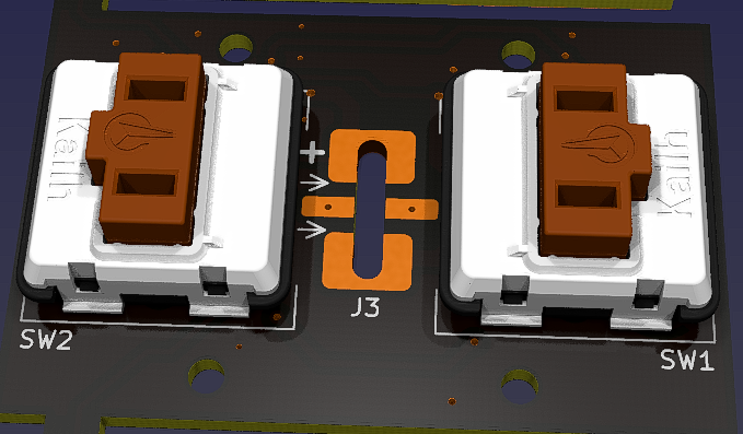
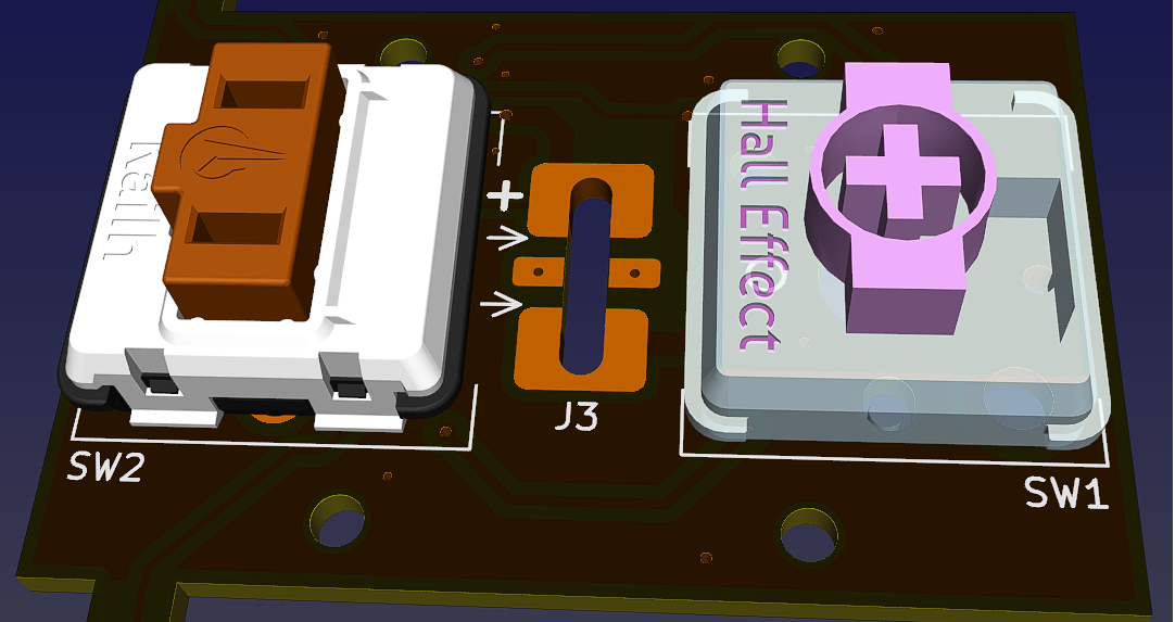
Main Board.Use either SW1 or SW2 footprint for Kailh Choc V1/V2 switches.
Use Kailh Choc low-profile hotswap socket if you choose hotswap PCB version.
https://kailhswitch.net/products/kailh-mechnical-keyboard-switches-hot-swap-pcb-socket-diy-for-1350-choc-low-profile-keyboard-switches
Short the corresponding jumper (sw1 or sw2) to enable the switch.
You can solder the other switch, but it's only for the feel, so don't short the jumper.
To connect to controller's Main Board:
This example shows SW1 as the trigger switch, and optional Choc V1 on SW2 is just for the feel.
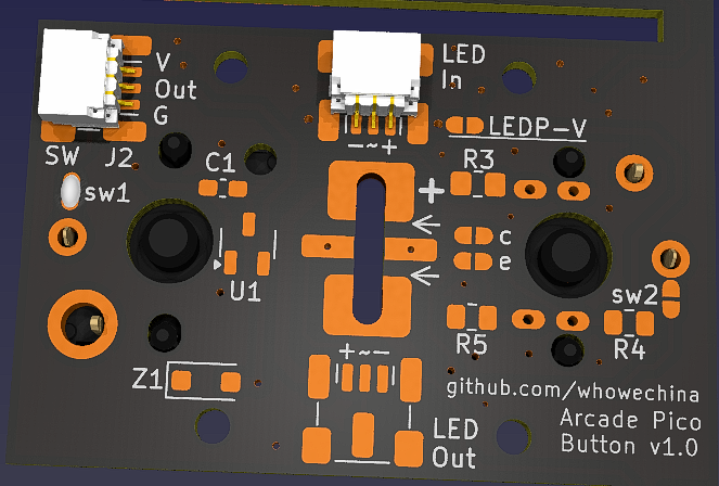
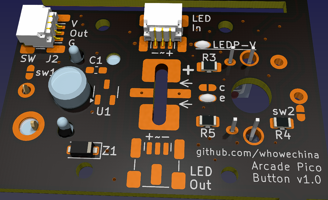
Solder the IR diode (IR908-7C) and phototransistor (PT908-7C) at proper height;
Solder R3 (500 ohm for 3.3V supply, 1k ohm for 5V supply);
Resistors: R4, R5; Jumpers: c, e; Zener: Z1.
You can solder a mechanical switch on SW1 footprint for some tactile feel, but don't short the jumper sw1.
On most systems, LED positive line is a constant 5V or 3.3V power supply, you can borrow that to power the optical sensor - just short the jumper "LEDP-V".
To connect to controller's Main Board:
This example shows a low-active configuration, 5V is borrowed from LED positive line, and optional Choc V1 on SW1 just for the feel.
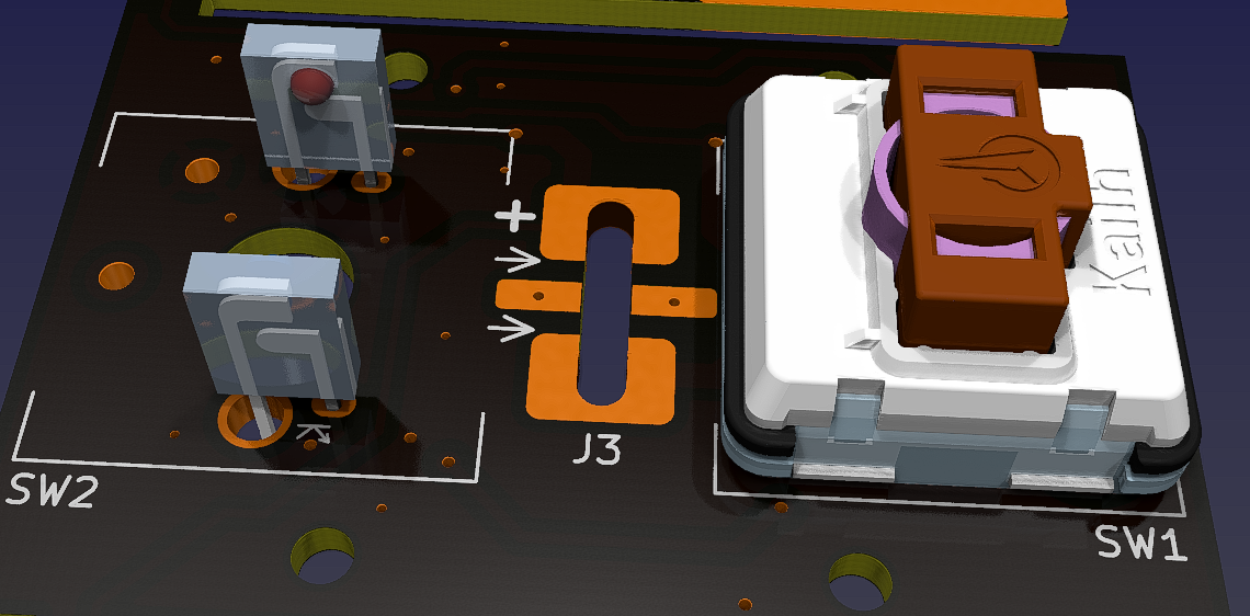
Magnetic switch is on SW1 footprint.
Solder U1 (SS49E SOT23-3) and C1 (0.1uF 0603).
You can install a mechanical switch on SW2 footprint for some tactile feel, but don't solder the jumper.
If the Hall effect switch is not mounted tightly, you may need to use some RTV silicone adhesive to secure it.
This example uses Hall effect switch on SW2 and optional Choc V1 on SW1 just for the feel.
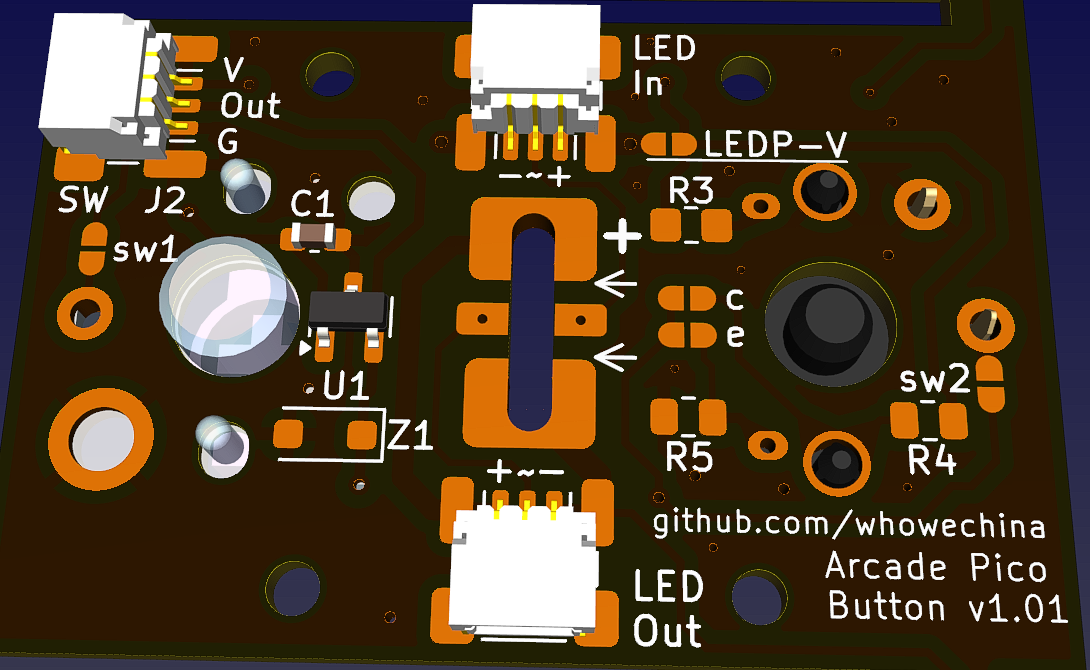
To connect to controller's Main Board:
"SW" connector (V, Out, G) connects to the Arcade Pico IO board. Then the IO Board connects to the Main Board.
Note that Arcade Pico IO Board is need for this setup.
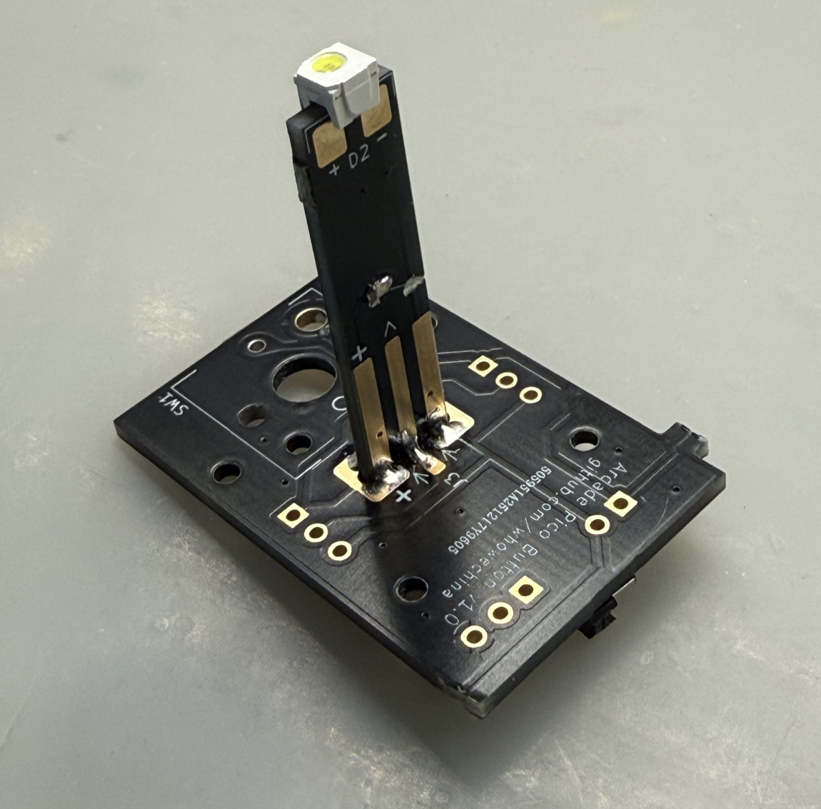
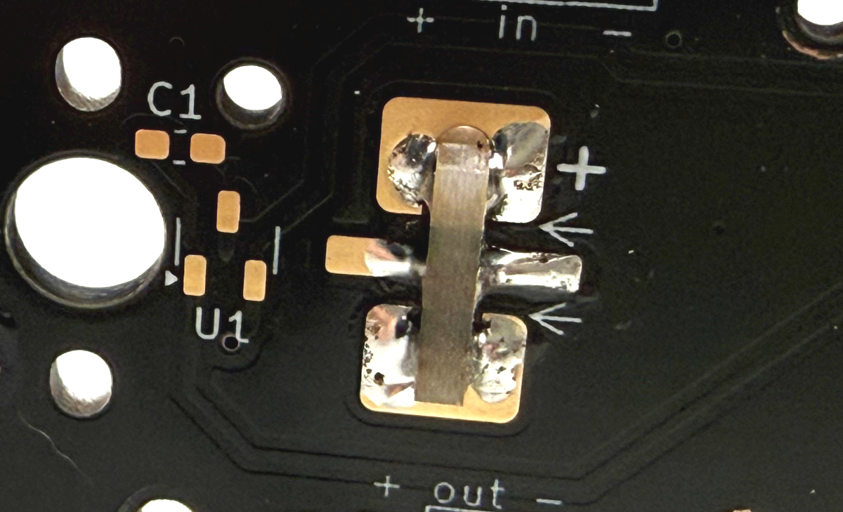
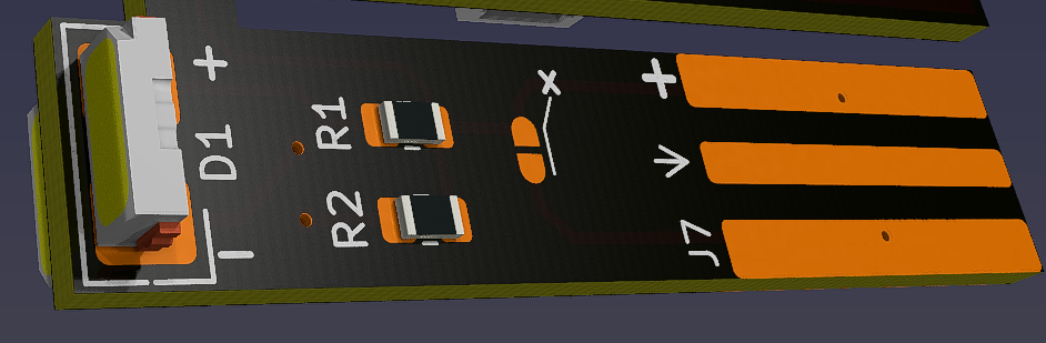
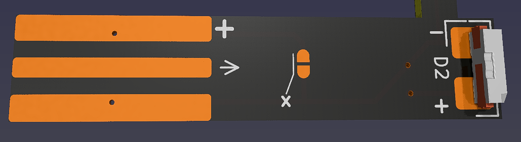
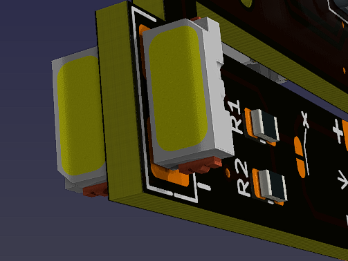
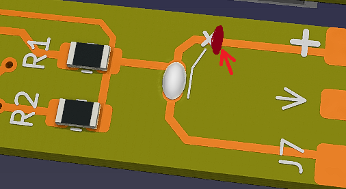
IO Board is required.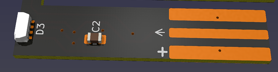
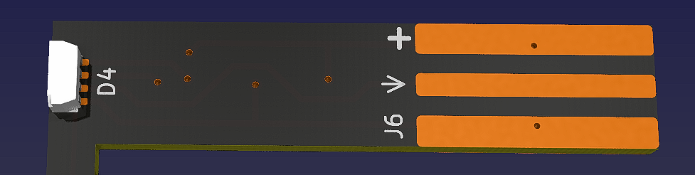
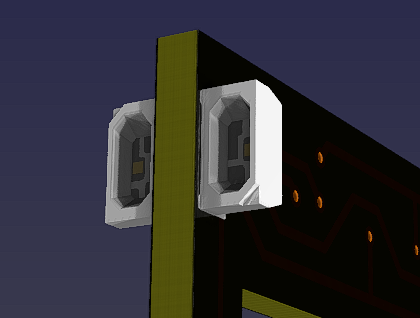
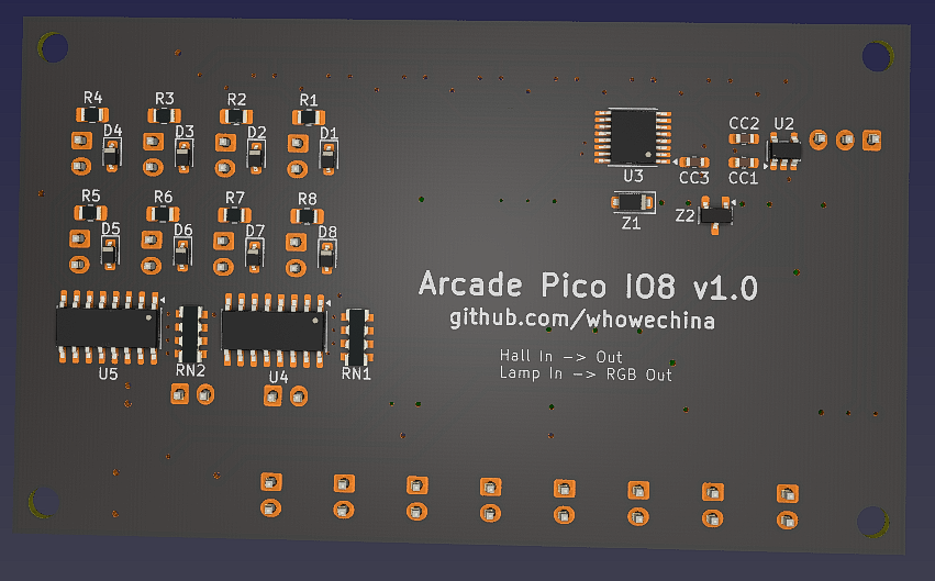
IO BoardIO Board can convert the analog signals from Hall effect switches into digital signals for your main controller board. It can also bridge traditional LED bulb signals to WS2812B RGB LED data signals.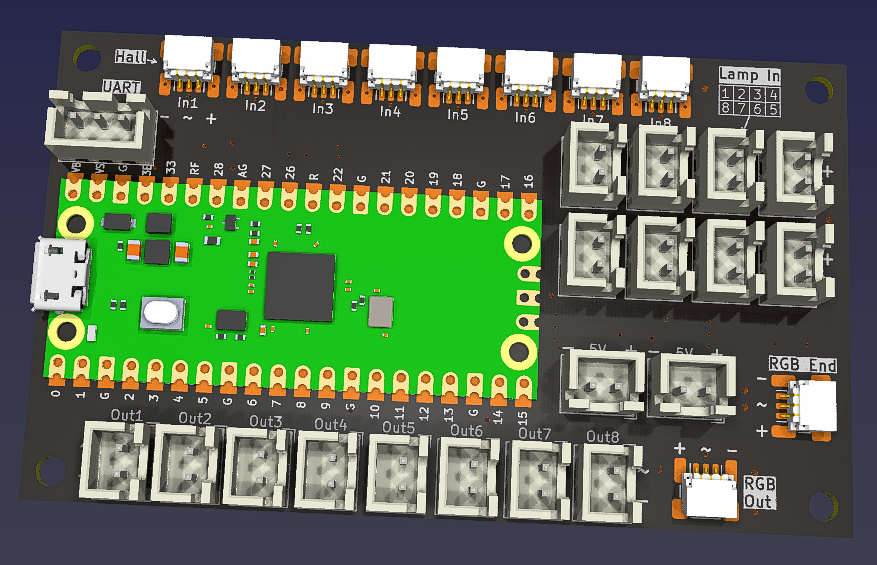
Button Boards.Button Board equipped with WS2812B RGB LED daughter board.Button Board and the one inside the optical isolator):
Use any FDM printer to print the body.
Files are in the "Production/3DPrint" folder.
Sanwa_push.stl - old style Sanwa lamp holder (push-click type).Sanwa_twist.stl - new style Sanwa lamp holder (twist-lock type).Samducksa.stl - Samducksa lamp holder.Chinese.stl - common Chinese button lamp holder.Use M2*6mm screws to secure the PCB to the button.
| Qty | Value | Footprint | References |
|---|---|---|---|
| 4 | ~ | button:M2_Screw | S1, S2, S3, S4 |
| 2 | 200 | Resistor_SMD:R_0805_2012Metric_Pad1.20x1.40mm_HandSolder | R1, R3 |
| 2 | 200 | Resistor_SMD:R_0805_2012Metric | R4, R5 |
| 2 | Gold Finger | button:GoldFinger | J6, J7 |
| 1 | 0.1uF | Capacitor_SMD:C_0805_2012Metric_Pad1.18x1.45mm_HandSolder | C2 |
| 1 | 0.1uF | Capacitor_SMD:C_0603_1608Metric_Pad1.08x0.95mm_HandSolder | C1 |
| 1 | 3.3V | Diode_SMD:D_SOD-123F | Z1 |
| 1 | Choc and IR Pair | button:SW_Kailh_Choc_IR_Combo | SW2 |
| 1 | Conn_01x03_Socket | button:SH1.0_3P_Solder_Combo | J2 |
| 1 | LED | button:DIPLED | D1 |
| 1 | LEDP-V | button:SolderJump | JP6 |
| 1 | Lamp Seat | button:LampSeat | J3 |
| 1 | RGB In | button:SH1.0_3P_Solder_Combo | J4 |
| 1 | RGB Out | button:SH1.0_3P_Solder_Combo | J5 |
| 1 | SS49E_SOT23 | button:SOT-23-FAT | U1 |
| 1 | WS2812B_Unified | button:WS2812B-DIP | D3 |
| 1 | c | button:SolderJump | JP3 |
| 1 | e | button:SolderJump | JP4 |
| 1 | sw1 | button:SolderJump | JP5 |
| 1 | sw2 | button:SolderJump | JP7 |
| 1 | ~ | button:Choc_HE | SW1 |


hackclub/OnBoard
💡 Join 1,000 teenagers and make your first PCB with a $100 grant!


CRImier/MyKiCad
My KiCad boards. Can't be bothered uploading individually anymore, so here you go.

pjgpetecodes/pico-streamdeck
This project is an OBS Controller using a Raspberry Pi Pico and CircuitPython.

freeDSP/freeDSP-aurora
freeDSP ADAU1452 with 8 analog input, 8 analog outputs, S/P-DIF I/O, ADAT I/O, USB Audio Class2, WiFi, Bluetooth

ugcs/ddc
Drone Show Software is software designed for drone shows, allowing flight path planning as well as control of dozens of drones simultaneously in a synchronized manner.
It measures 40 × 46 mm and has 2 copper layers, 1.6 mm thick.
27 parts. The full list of its parts is on this page, with links to each part's symbol and footprint where PCBKit's library has them.
From the whowechina/arcade_pico repository on GitHub, at the commit this page was made from: the board is PCB/button_dip_led/button.kicad_pcb and its schematic PCB/button/button.kicad_sch. PCBKit opens the board in the browser, with nothing to install.
Its repository states no licence, so its author keeps all rights: ask whowechina before reusing the design.
