6 layers84 × 50 mm
Solar ribbit
Ribbit-Network/ribbit-network-frog-hardware
The sensor for the world's largest crowdsourced network of open-source, low-cost, GHG Gas Detection Sensors.
171 parts107MIT

 whoelse091/MAXWELLS0S1
Open-source LoRa mesh that relays a hiker's SOS + GPS across cellular-dark mountains to Mountain Rescue. No GSM, no internet. Hardware under CERN-OHL-S.
LORASOS is an open-source printed circuit board by whoelse091, from the whoelse091/MAXWELLS0S repository on GitHub. It is a 4-layer board of 55 × 80 mm with 49 parts on 47 nets, routed with 364 tracks and 151 vias.
It is built around the SAM-M10Q-00B, TPS631010YBGR and BQ25185DLHR, with the BAT54J among its other parts. Its parts include 14 resistors, 11 capacitors, 4 ICs, 4 diodes and 3 connectors. It belongs with the radio and wireless boards and the STM32 boards of this library.



Emergency comms for the mountains.
Solar-powered, long-range LoRa mesh that carries a hiker's distress call
across cellular-dark terrain — straight to Mountain Rescue.


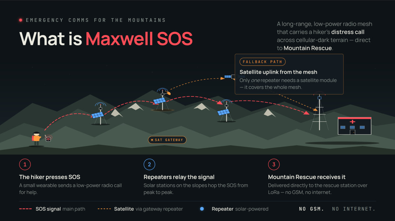
A long-range, low-power radio mesh that carries a hiker's distress call across terrain with no cellular coverage — delivered directly to a mountain rescue station over LoRa. No GSM. No internet.
Satellite fallback: only one repeater in the mesh needs a satellite module — it provides an uplink for the entire network.
Meshtastic is a great general-purpose LoRa mesh — text chat, position sharing, telemetry, channels, encryption, MQTT bridging, phone pairing. That generality is the whole point of it, but it also means the protocol carries a lot of machinery an emergency beacon never needs.
Maxwell SOS does exactly one thing: get a distress call + GPS fix out, reliably, on the worst day. Stripping everything an SOS doesn't need lets us optimize hard for that:
You could bolt an SOS onto Meshtastic — but you'd drag its whole feature set along to do it. Maxwell starts from the emergency case and builds only that.
Core of the beacon / repeater node:
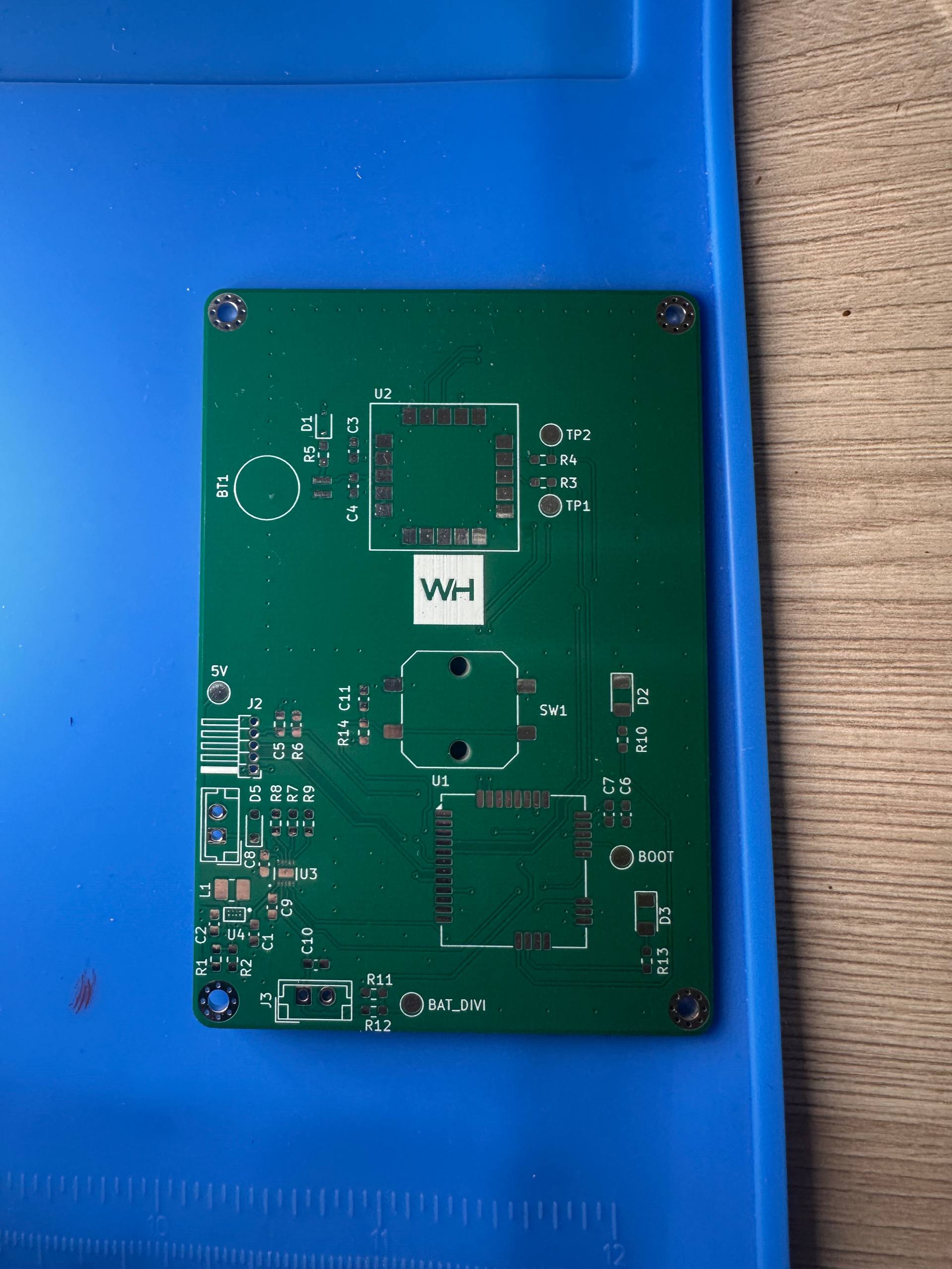
Bare PCB — rev. A, as received from fab |
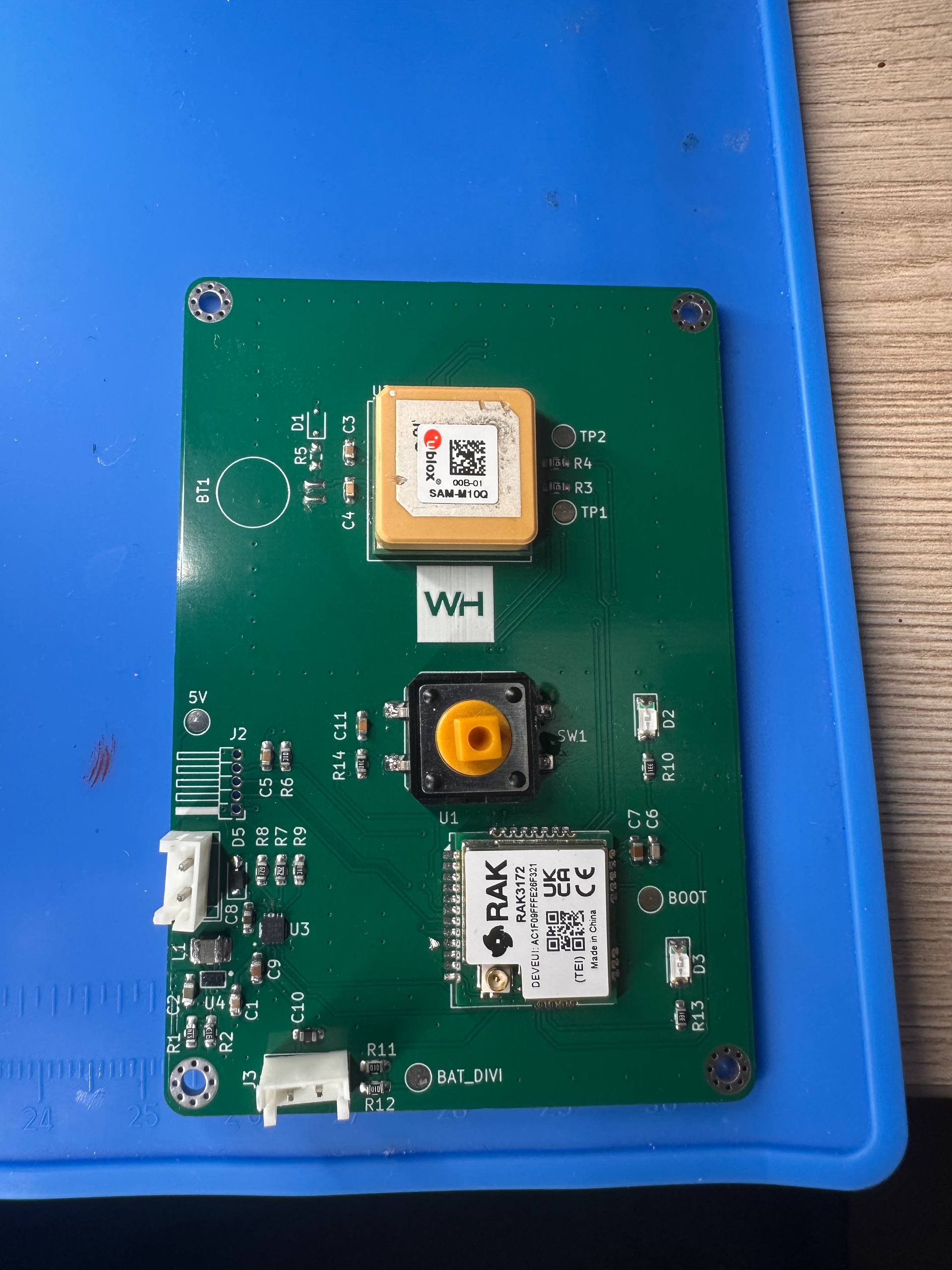
Assembled — hand-soldered first article |
Core of the beacon / repeater node:
Full bill of materials lives in hardware/.
MAXWELLS0S/
├── assets/                 logo, renders, photos
├── docs/                   documentation
├── hardware/               KiCad sources, schematic, BOM
│   └── WEARBALE-DEVICE/    wearable beacon (schematic + README)
├── protocol/               mesh protocol specification
├── .gitignore
├── LICENSE
└── README.md✅ Hardware design done — now in testing. The beacon schematic is complete and under bench testing. Detailed test results, firmware and full documentation are coming a bit later.
Maxwell SOS is an experimental, open-source project. It is not a certified safety device and does not replace a PLB/EPIRB on 406 MHz (COSPAS–SARSAT). A LoRa mesh does not guarantee message delivery — it depends on repeaters being in range. Never rely on this device as your only means of rescue. You are responsible for complying with local ISM-band regulations (EU868 / US915 / etc.).
Hardware design files are licensed under CERN-OHL-S v2 (strongly reciprocal).
See LICENSE.
RESILIENCE FIRST
| Qty | Value | Footprint | References |
|---|---|---|---|
| 4 | MountingHole_Pad | MountingHole:MountingHole_2.2mm_M2_Pad_Via | H1, H2, H3, H4 |
| 3 | 0.1uF | Capacitor_SMD:C_0603_1608Metric_Pad1.08x0.95mm_HandSolder | C3, C4, C11 |
| 3 | 10k | Resistor_SMD:R_0603_1608Metric_Pad0.98x0.95mm_HandSolder | R6, R9, R14 |
| 3 | 10uF | Capacitor_SMD:C_0603_1608Metric_Pad1.08x0.95mm_HandSolder | C1, C7, C9 |
| 2 | 100k | Resistor_SMD:R_0603_1608Metric_Pad0.98x0.95mm_HandSolder | R11, R12 |
| 2 | 1uF | Capacitor_SMD:C_0603_1608Metric_Pad1.08x0.95mm_HandSolder | C8, C10 |
| 2 | 220 | Resistor_SMD:R_0603_1608Metric_Pad0.98x0.95mm_HandSolder | R10, R13 |
| 2 | 470 | Resistor_SMD:R_0603_1608Metric_Pad0.98x0.95mm_HandSolder | R3, R4 |
| 2 | LED | LED_SMD:LED_1206_3216Metric_Pad1.42x1.75mm_HandSolder | D2, D3 |
| 2 | RX | TestPoint:TestPoint_Pad_D2.0mm | 5V, TP2 |
| 1 | 100nF | Capacitor_SMD:C_0603_1608Metric_Pad1.08x0.95mm_HandSolder | C5 |
| 1 | 100uF | Capacitor_SMD:C_0603_1608Metric_Pad1.08x0.95mm_HandSolder | C6 |
| 1 | 1uH | Inductor_SMD:L_1008_2520Metric_Pad1.43x2.20mm_HandSolder | L1 |
| 1 | 2.4k | Resistor_SMD:R_0603_1608Metric_Pad0.98x0.95mm_HandSolder | R7 |
| 1 | 3.3k | Resistor_SMD:R_0603_1608Metric_Pad0.98x0.95mm_HandSolder | R5 |
| 1 | 47uF | Capacitor_SMD:C_0603_1608Metric_Pad1.08x0.95mm_HandSolder | C2 |
| 1 | 511k | Resistor_SMD:R_0603_1608Metric_Pad0.98x0.95mm_HandSolder | R1 |
| 1 | 600 | Resistor_SMD:R_0603_1608Metric_Pad0.98x0.95mm_HandSolder | R8 |
| 1 | 91k | Resistor_SMD:R_0603_1608Metric_Pad0.98x0.95mm_HandSolder | R2 |
| 1 | BAT54J | Diode_SMD:D_SOD-323F | D1 |
| 1 | BATTERY_CON | Connector_JST:JST_EH_B2B-EH-A_1x02_P2.50mm_Vertical | J3 |
| 1 | BAT_M | TestPoint:TestPoint_Pad_D2.0mm | BAT_DIVI |
| 1 | BOOT | TestPoint:TestPoint_Pad_D2.0mm | BOOT |
| 1 | BQ25185DLHR | BQ25185:WSON10_DLH_TEX-L | U3 |
| 1 | Battery_Cell | Battery:BatteryHolder_Seiko_MS621F | BT1 |
| 1 | CHARGER_CON | Connector_JST:JST_EH_B2B-EH-A_1x02_P2.50mm_Vertical | J1 |
| 1 | LOGO | LOGO | G*** |
| 1 | RAK3172-xx-8-SM-xI | RF_Module:RAK3172 | U1 |
| 1 | SAM-M10Q-00B | SAM-M10Q-00B:SAM-M10Q_UBL | U2 |
| 1 | STM32_PROG | Connector_PinHeader_1.27mm:PinHeader_1x05_P1.27mm_Horizontal | J2 |
| 1 | SW_Push_Dual_x2 | Button_Switch_SMD:SW_Push_1P1T_NO_CK_PTS125Sx73PSMTR | SW1 |
| 1 | TPS631010YBGR | TPS631010:YBG0008-IPC_A | U4 |
| 1 | TSD05 | Diode_SMD:D_SOD-323_HandSoldering | D5 |
| 1 | TX | TestPoint:TestPoint_Pad_D2.0mm | TP1 |
It measures 55 × 80 mm and has 4 copper layers, 1.6 mm thick.
49 parts, built around the SAM-M10Q-00B, TPS631010YBGR, BQ25185DLHR and BAT54J. The full list of its parts is on this page, with links to each part's symbol and footprint where PCBKit's library has them.
From the whoelse091/MAXWELLS0S repository on GitHub, at the commit this page was made from: the board is hardware/WEARBALE-DEVICE/Kikad-files/LORASOS.kicad_pcb and its schematic hardware/WEARBALE-DEVICE/Kikad-files/LORASOS.kicad_sch. PCBKit opens the board in the browser, with nothing to install.
Its repository states no licence, so its author keeps all rights: ask whoelse091 before reusing the design.
Ribbit-Network/ribbit-network-frog-hardware
The sensor for the world's largest crowdsourced network of open-source, low-cost, GHG Gas Detection Sensors.

Pegoku/Home-Assistant-Control-pad
This is a programmable Home Assistant Control Pad. It can control 4 Home assistant devices at a time, and has 4 togglable screens/zones (in total 16 devices).


uge/trk
This repo contains a KiCad 8.0 project which hopes to implement a low power tracker for pico-balloons based on the nRF9151 module and a WSPR protocol modulator.


anchit92/Open-Source-RaceBox-mini-Emulator
Open Source RaceBox mini emulator

bobberdolle1/SkySweep32
Open-source passive multi-band RF monitoring system | 855–925 MHz, 2.4 GHz, 5.8 GHz | Rev C first prototype

JGAguado/LIA
Low-power pet tracking platform built around Meshtastic and LoRa mesh networking