
4 layers44.1 × 50 mm

 whatwareweb/usb-dac2
USB DAC based on PCM2912A IC
Usb dac is an open-source printed circuit board by whatwareweb, from the whatwareweb/usb-dac repository on GitHub, published under the CERN-OHL-S-2.0 licence. It is a 2-layer board of 82.5 × 39 mm with 28 parts on 28 nets, routed with 205 tracks and 0 vias.
It is built around the PCM2912APJTR. Its parts include 14 capacitors, 9 resistors, 2 connectors, 1 IC and 1 inductor. It belongs with the audio and music boards of this library.
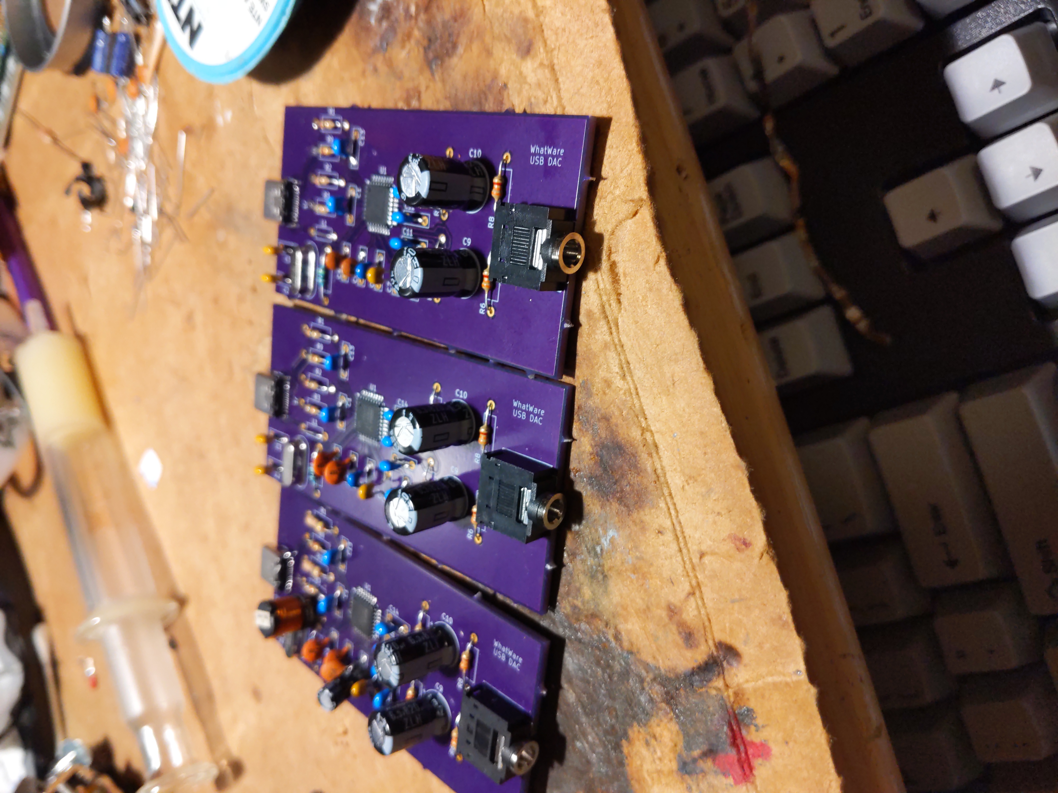
USB DAC based on TI PCM2912A IC
This design is tested and working, I use it as my daily driver DAC
I ordered my pcbs from OSHpark, the project link is here for a 1-click order that is already configured and will work well https://oshpark.com/shared_projects/iy0FjLmS
This DAC has been designed with good low-frequency response in mind, large output capacitors are used to ensure very low frequencies can be reproduced
To adjust high-frequency response, C4 and C5 can be decreased to allow higher-frequency sounds to make it to the output. Too high of a capacitance for either of these will lead to a muffled sound
C9 and C10 are the output capacitors, the Rubycon model listed in the BOM does very well for the price but they can be swapped out for any higher quality electrolytic capacitor with the same lead spacing. to increase LF response make these a larger value, to decrease make them a smaller value. I just used these as I had like 70 of them spare from another project
Check the assembly directory for assembly pictures
This board design is tested and working, but if you would like any help you can open a github issue and I'll try my best (no i will most likely not give you one for free, sorry)
During assembly it is very helpful to open the board view in KiCad to see the component values and the BOM
This board has been designed with easy assembly in mind, there are only 2 SMD parts which you could get assembled for you at a PCB assembly service, the rest of the parts are through-hole and very easy to solder DIY.
The parts in the BOM can all be purchased at Mouser electronics (DigiKey probably has them too, I didn't check)
I just went with the cheapest option of the rated component value with a minimum voltage rating of 5v, so if you need to get components from some other supplier you can do that as well and it will probably work, just make sure to double-check the lead spacing for the capacitors, inductors, etc
To export the BOM, open the schematic in Kicad, and click the BOM icon in the toolbar, from there you can copy/paste or export
| Qty | Value | Footprint | References |
|---|---|---|---|
| 6 | 1uF | Capacitor_THT:C_Rect_L7.0mm_W2.0mm_P5.00mm | C1, C8, C11, C12, C13, C14 |
| 4 | 3.3k | Resistor_THT:R_Axial_DIN0207_L6.3mm_D2.5mm_P10.16mm_Horizontal | R5, R6, R7, R8 |
| 2 | 100pF | Capacitor_THT:C_Rect_L7.0mm_W2.0mm_P5.00mm | C4, C5 |
| 2 | 30 | Resistor_THT:R_Axial_DIN0207_L6.3mm_D2.5mm_P10.16mm_Horizontal | R1, R2 |
| 2 | 30pF | Capacitor_THT:C_Rect_L7.0mm_W2.0mm_P5.00mm | C2, C3 |
| 2 | 820uF | Capacitor_THT:CP_Radial_D8.0mm_P3.50mm | C9, C10 |
| 1 | 0.1uF | Capacitor_THT:C_Rect_L7.0mm_W2.0mm_P5.00mm | C7 |
| 1 | 1.5k | Resistor_THT:R_Axial_DIN0207_L6.3mm_D2.5mm_P10.16mm_Horizontal | R3 |
| 1 | 1M | Resistor_THT:R_Axial_DIN0207_L6.3mm_D2.5mm_P10.16mm_Horizontal | R4 |
| 1 | 1uH | Inductor_THT:L_Axial_L5.3mm_D2.2mm_P7.62mm_Horizontal_Vishay_IM-1 | L1 |
| 1 | 3.3uF | Capacitor_THT:C_Rect_L7.0mm_W2.0mm_P5.00mm | C6 |
| 1 | 5.1k | Resistor_THT:R_Axial_DIN0207_L6.3mm_D2.5mm_P10.16mm_Horizontal | R9 |
| 1 | 6 MHz | Crystal:Crystal_HC49-U_Vertical | Y1 |
| 1 | AudioJack3 | Connector_Audio:Jack_3.5mm_CUI_SJ1-3523N_Horizontal | J2 |
| 1 | PCM2912APJTR | Package_QFP:TQFP-32_7x7mm_P0.8mm | U1 |
| 1 | USB_C_Receptacle_USB2.0_14P | Connector_USB:USB_C_Receptacle_GCT_USB4105-xx-A_16P_TopMnt_Horizontal | J1 |
It measures 82.5 × 39 mm and has 2 copper layers, 1.6 mm thick.
28 parts, built around the PCM2912APJTR. The full list of its parts is on this page, with links to each part's symbol and footprint where PCBKit's library has them.
From the whatwareweb/usb-dac repository on GitHub, at the commit this page was made from: the board is usb-dac.kicad_pcb and its schematic usb-dac.kicad_sch. PCBKit opens the board in the browser, with nothing to install.
Its repository publishes it under the CERN-OHL-S-2.0 licence: you may reuse it on that licence's terms (keep the author's notice, and for a copyleft licence share your changes alike).

ANSHUMANDOCX/USB-C-AUDIO-HUB
This is a USB C Hub which had a Audio IN/OUT Along with 3 USB ports.

Hasnat4763/audio-i-love
AudioCardio is an Audio Card I designed which uses PCM2912A Audio IC to connect to your pc and use it as an audio Card

moonbeeper/echowawa
Your typical DAC with bluetooth audio (with possible upgrades to use WiFi sources) and a USB C as an AUX port. It can output to either RCA jacks or a headphone jack.


tracelabs-pcb/usb-audio-interface
USB-C Audio Interface PCB — UAC2, Headset, Mic Preamp — KiCad 4-Layer

joeycastillo/Sensor-Watch
A board replacement for the classic Casio F-91W wristwatch