2 layers39.8 × 60 mm

 whati001/tuff-tuff-light
Trailer light for every tuff tuff tracor on earch
Tuff tuff pcb is an open-source printed circuit board by whati001, from the whati001/tuff-tuff-light repository on GitHub, published under the MIT licence. It is a 2-layer board of 50 × 80 mm with 48 parts on 84 nets, routed with 273 tracks and 35 vias.
It is built around the MT3608, DMG2301L and DMG3402L, with the SS34 among its other parts. Its parts include 14 resistors, 8 transistors, 5 connectors, 4 capacitors and 3 ICs.


A robust, modular, and completely wireless trailer lighting system designed for agricultural machinery, utilizing BLE communication. Built on the nRF52840 SoC and developed with the Zephyr RTOS, this project includes custom-designed PCBs and 3D printed enclosures for reliable field use. The choose design enables seamless connectivity without complicated pairing procedures and also allows to connect up to infinite receiver lights to a single sender.
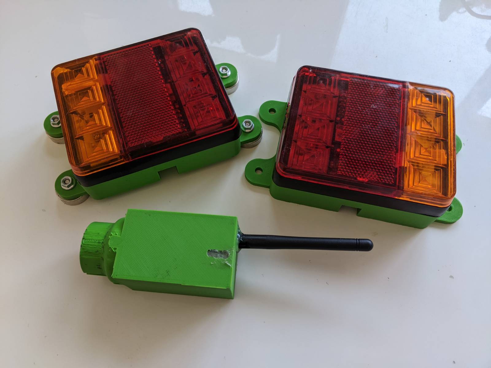
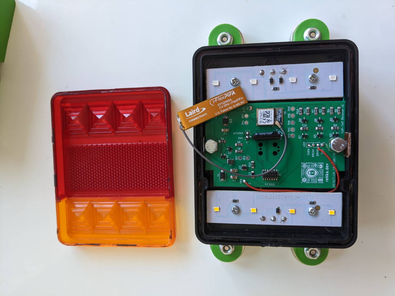
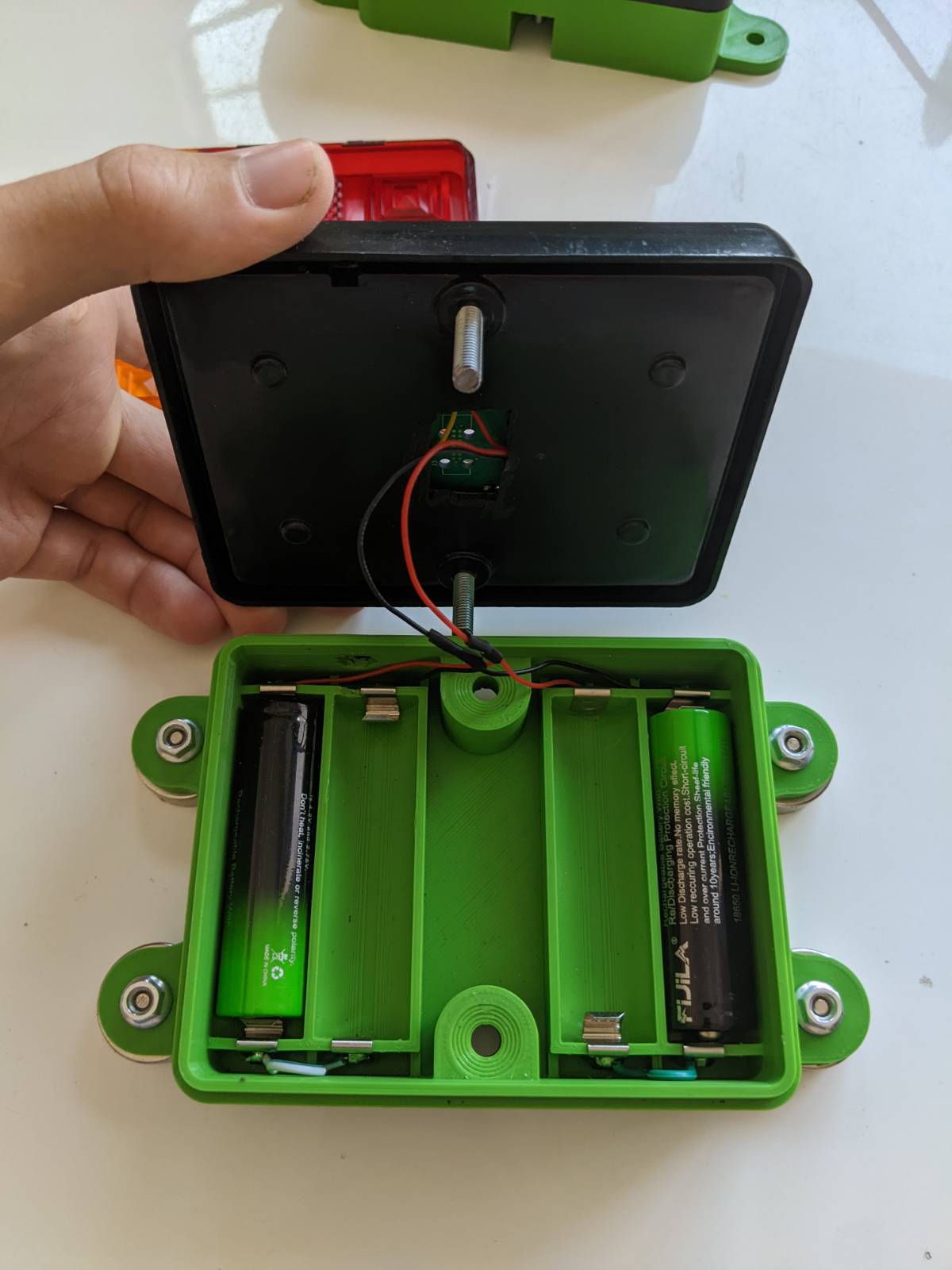
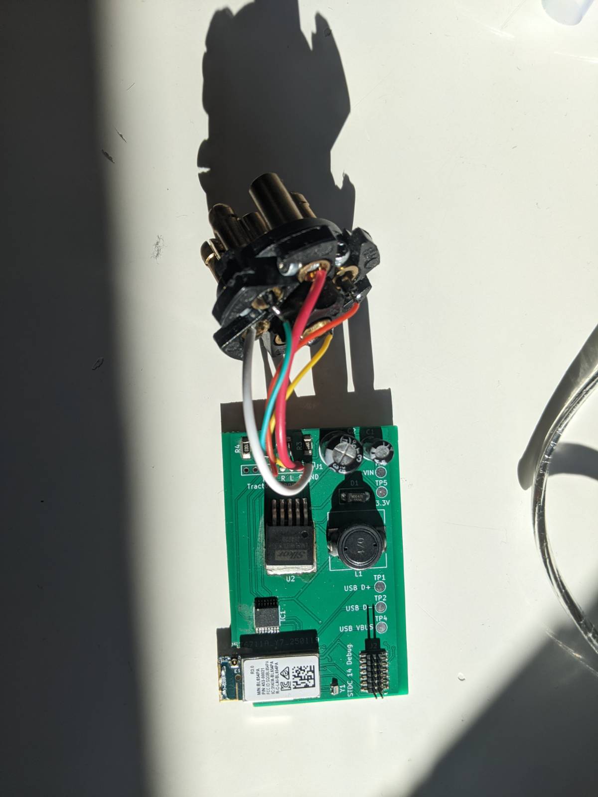

The project is structured as follows.
.
├── 3d/             # 3d printer files
├── applications/
│ ├── ttl_sender/   # ttl sender code
│ └── ttl_receiver/ # ttl receiver code
├── boards/         # custom boards definition
├── pcb/            # custom pcb KiCad files
...
└── README.mdFirst we need to initiate a python environment and install west. Afterwards, we initiate the Zephyr workspace.
python -m venv ./env
<activate venv>
pip install west
west init -m https://github.com/whati001/tuff-tuff-light tuff_tuff_light
cd tuff_tuff_light
west updateNavigate into the workspace directory and run:
# build sender
west build -b ttlv1_pa/nrf52840 ttl/applications/ttl_sender

# build receiver
west build -b ttlv1/nrf52840 ttl/applications/ttl_senderConnect your debugger and run:
west flashTransmitter: Reads trailer socket signals and broadcasts light commands via BLE. Receiver Modules: Interpret BLE commands and control LEDs accordingly.
PCBs
Enclosures
The project aims just to be a minimal viable project (MVP), so there is not much testing included.
This project is licensed under the MIT License. See the LICENSE file for details.
Contributions are welcome! If you'd like to add features (e.g., low battery warnings, OTA updates), feel free to open a PR or issue. If you are interested to turn this MVP into a real project, please get in touch with me.
Here are a few ideas and enhancements planned or recommended for future development:
🔋 Battery Charging Currently, power is restored by manually replacing the 18650 batteries. The proposed improvement is to integrate a charging circuit directly into the 3D-printed enclosure, enabling in-place recharging and eliminating the need to open the housing. At the same time, the design would retain compatibility with swappable battery modules, allowing a quick base replacement in scenarios where charging time is a limiting factor.
🚦 Expanded Signal Set Extend support for additional signal inputs from the standard 7-pin trailer connector, including reverse, brake, fog lights, and more. Furthermore, the system’s modular architecture enables the integration of entirely new light types, such as side marker lights (e.g., white delimiting lights along the trailer’s sides), enhancing both functionality and visibility.
🌧️ Weatherproofing Enhancements Improve gasket seals in the 3D printed case and verify IP rating in outdoor environments.
📘 Documentation Expansion Add detailed firmware architecture docs and schematic walkthroughs.
For questions, suggestions, or demo requests, feel free to contact [whati001@outlook.com] or open a GitHub issue
| Qty | Value | Footprint | References |
|---|---|---|---|
| 8 | 100k | Resistor_SMD:R_1206_3216Metric_Pad1.30x1.75mm_HandSolder | R2, R3, R5, R6, R8, R9, R11, R12 |
| 7 | TestPoint | TestPoint:TestPoint_Pad_D2.0mm | TP1, TP2, TP3, TP4, TP5, TP6, TP8 |
| 4 | 10R | Resistor_SMD:R_1206_3216Metric_Pad1.30x1.75mm_HandSolder | R1, R4, R7, R10 |
| 4 | DMG2301L | Package_TO_SOT_SMD:SOT-23 | Q1, Q3, Q5, Q7 |
| 4 | DMG3402L | Package_TO_SOT_SMD:SOT-23 | Q2, Q4, Q6, Q8 |
| 2 | 22u | Capacitor_SMD:C_1206_3216Metric_Pad1.33x1.80mm_HandSolder | C3, C4 |
| 1 | 1u | Capacitor_SMD:C_1206_3216Metric_Pad1.33x1.80mm_HandSolder | C1 |
| 1 | 2.2k | Resistor_SMD:R_1206_3216Metric_Pad1.30x1.75mm_HandSolder | R14 |
| 1 | 2.2u | Capacitor_SMD:C_1206_3216Metric_Pad1.33x1.80mm_HandSolder | C2 |
| 1 | 42k | Resistor_SMD:R_1206_3216Metric_Pad1.30x1.75mm_HandSolder | R13 |
| 1 | 451-00001 | TTF_Lib:XCVR_451-00001 | U1 |
| 1 | Conn_01x02_Pin | Connector_PinSocket_2.54mm:PinSocket_1x02_P2.54mm_Vertical | J4 |
| 1 | Conn_01x02_Socket | Connector_PinHeader_2.54mm:PinHeader_1x02_P2.54mm_Vertical | J1 |
| 1 | Conn_01x04_Pin | Connector_PinHeader_2.54mm:PinHeader_1x04_P2.54mm_Vertical | J5 |
| 1 | Conn_ST_STDC14 | Connector_PinHeader_1.27mm:PinHeader_2x07_P1.27mm_Vertical_SMD | J2 |
| 1 | Crystal | Crystal:Crystal_SMD_MicroCrystal_CC8V-T1A-2Pin_2.0x1.2mm | Y1 |
| 1 | IN BOOSTER | TestPoint:TestPoint_Pad_D2.0mm | TP7 |
| 1 | L22u | Inductor_SMD:L_1210_3225Metric | L1 |
| 1 | LOGO | TTF_Lib:rehka_image | G*** |
| 1 | MT3608 | Package_TO_SOT_SMD:SOT-23-6 | U3 |
| 1 | ON BOOSTER | TestPoint:TestPoint_Pad_D2.0mm | TP9 |
| 1 | OUT BOOSTER | TestPoint:TestPoint_Pad_D2.0mm | TP9 |
| 1 | SS34 | Diode_SMD:D_SMA | D1 |
| 1 | TC2070-IDC | TTF_Lib:TAG-CONNECT_TC2070-IDC | J3 |
| 1 | TLV76733QWDRBxQ1 | TTF_Lib:SOP65P490X110-9N | U2 |


TheContrappostoShop/Apollo
Control Board for the Prometheus mSLA Printer.


It measures 50 × 80 mm and has 2 copper layers, 1.6 mm thick.
48 parts, built around the MT3608, DMG2301L, DMG3402L and SS34. The full list of its parts is on this page, with links to each part's symbol and footprint where PCBKit's library has them.
From the whati001/tuff-tuff-light repository on GitHub, at the commit this page was made from: the board is pcb/ttf_receiver_v1/tuff_tuff_pcb.kicad_pcb and its schematic pcb/ttf_receiver_v1/tuff_tuff_pcb.kicad_sch. PCBKit opens the board in the browser, with nothing to install.
Its repository publishes it under the MIT licence: you may reuse it on that licence's terms (keep the author's notice, and for a copyleft licence share your changes alike).