2 layers36.8 × 34.7 mm
Tinylab proto1
espotek-org/Labrador
EspoTek Labrador is a USB device that transforms your PC or smartphone into a fully-featured electronics lab. This repo holds all of the source code!
79 parts1.2k
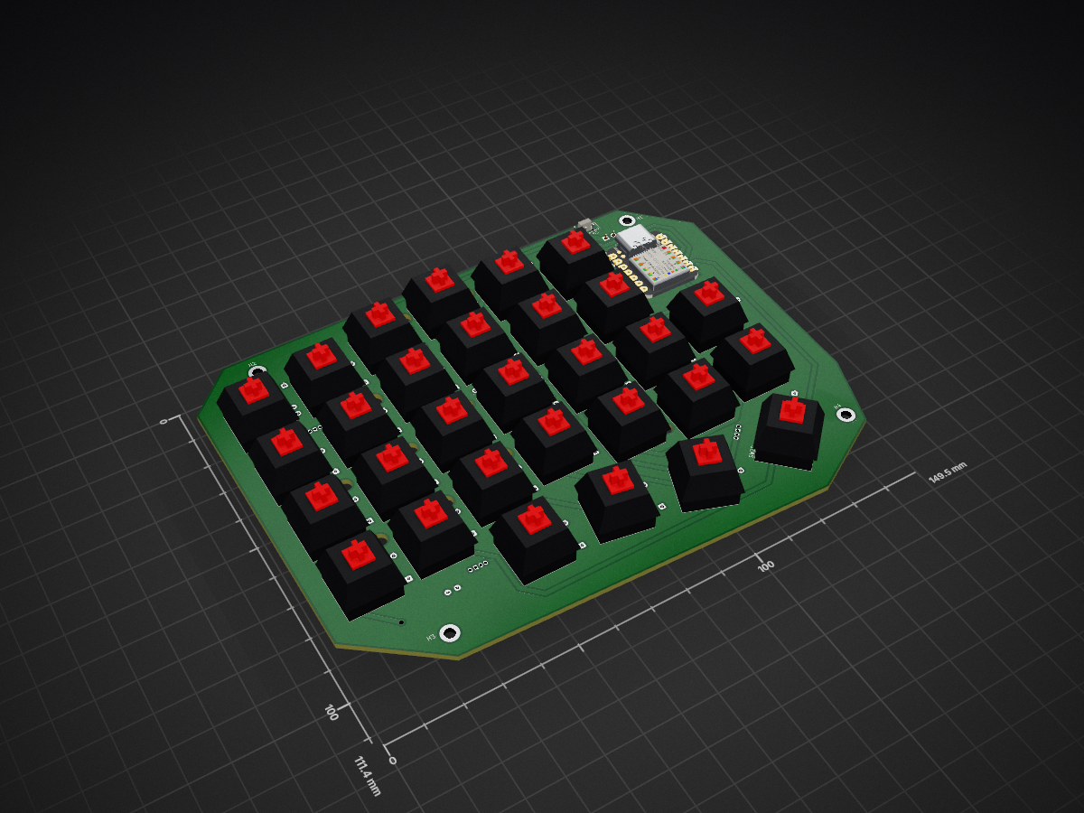
 WGRL/split-keyboard
Split keyboard with ble and usb. Custom pcb based on nrf52840 mcu module with specific firmware written in C (Zephyr)
Left side is an open-source printed circuit board by WGRL, from the WGRL/split-keyboard repository on GitHub, published under the GPL-3.0 licence. It is a 2-layer board of 149.5 × 111.4 mm with 79 parts on 53 nets, routed with 352 tracks and 5 vias.
Its parts include 30 diodes, 30 switches, 6 capacitors, 6 ICs and 1 resistor. It belongs with the keyboards and input and radio and wireless boards and the nRF52 and nRF5x boards of this library.
Split keyboard with ble and usb. Custom pcb based on nrf52840 mcu module with specific firmware written in C (Zephyr)
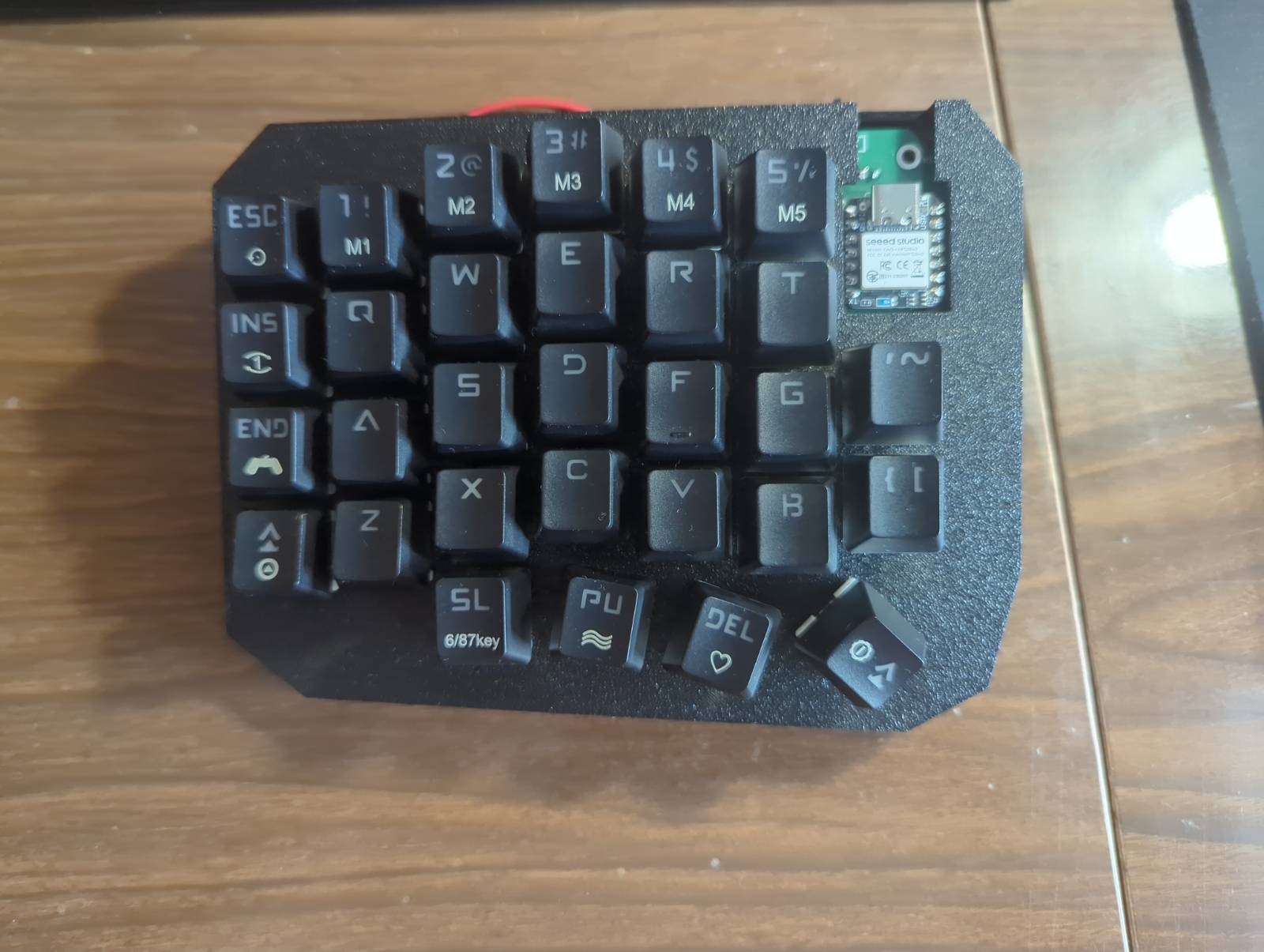
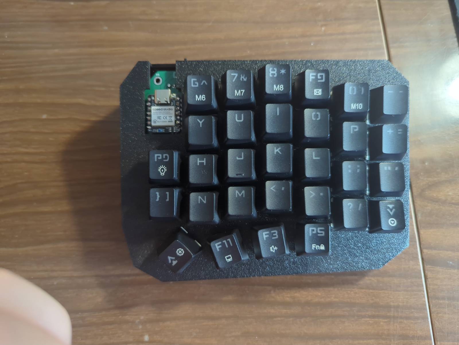
All the firmware is stored in software directory. It also contains all the configs for Zephyr, Kconfig, CMAKE, scripts etc.
The source code is stored in software/src.
The right side connects to the left one using Bluetooth. It sends the hid codes of clicked keys with approximately 12 ms intervals. The left side takes together keys clicked on left and right side and sends it to the PC using eithter Bluetooth or USB. USB and Bluetooth are automatically switched. If the USB connection is detected it is a chosen communication method. If there is no USB connection then left side starts Bluetooth advertising or automatically connects to the PC if there is bonding already.
The name of the device is automatically WGRL_KEYBOARD, but you can change it in software/config/prj_left.conf in the # Names section.
To program the mcu you use eithter
./scripts/run.sh left or ./scripts/run.sh right
depending on the side
The files for printed PCBs are stored in hardware directory.
This is for personal use so note that the boards don't have any ESD, reverse polarity, overvoltage protection etc. Also it lacks extra capacitor to sustain battery voltage.
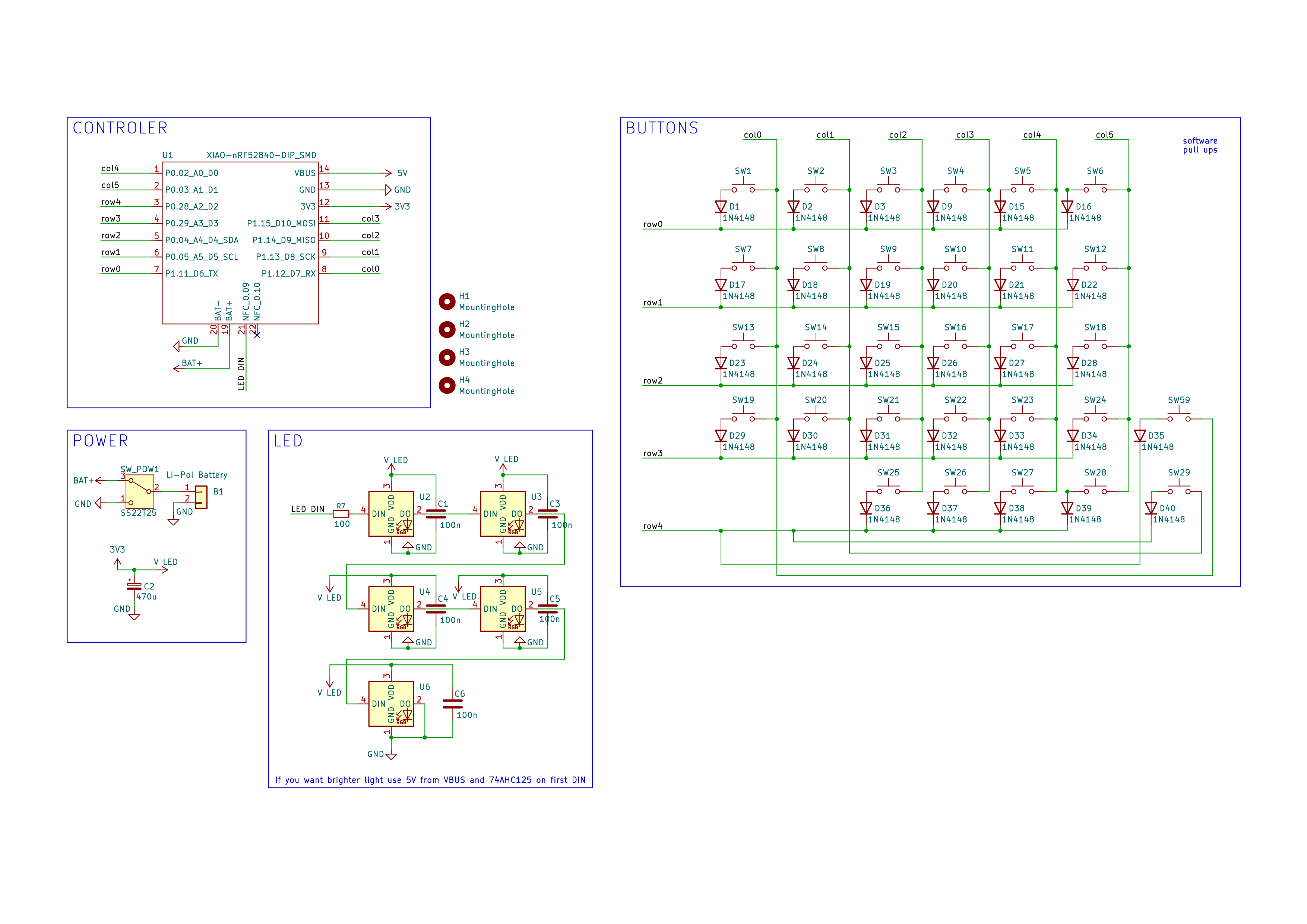
Printed PCBs. The files are in hardware directory. They are based on only THT elements for easier soldering.
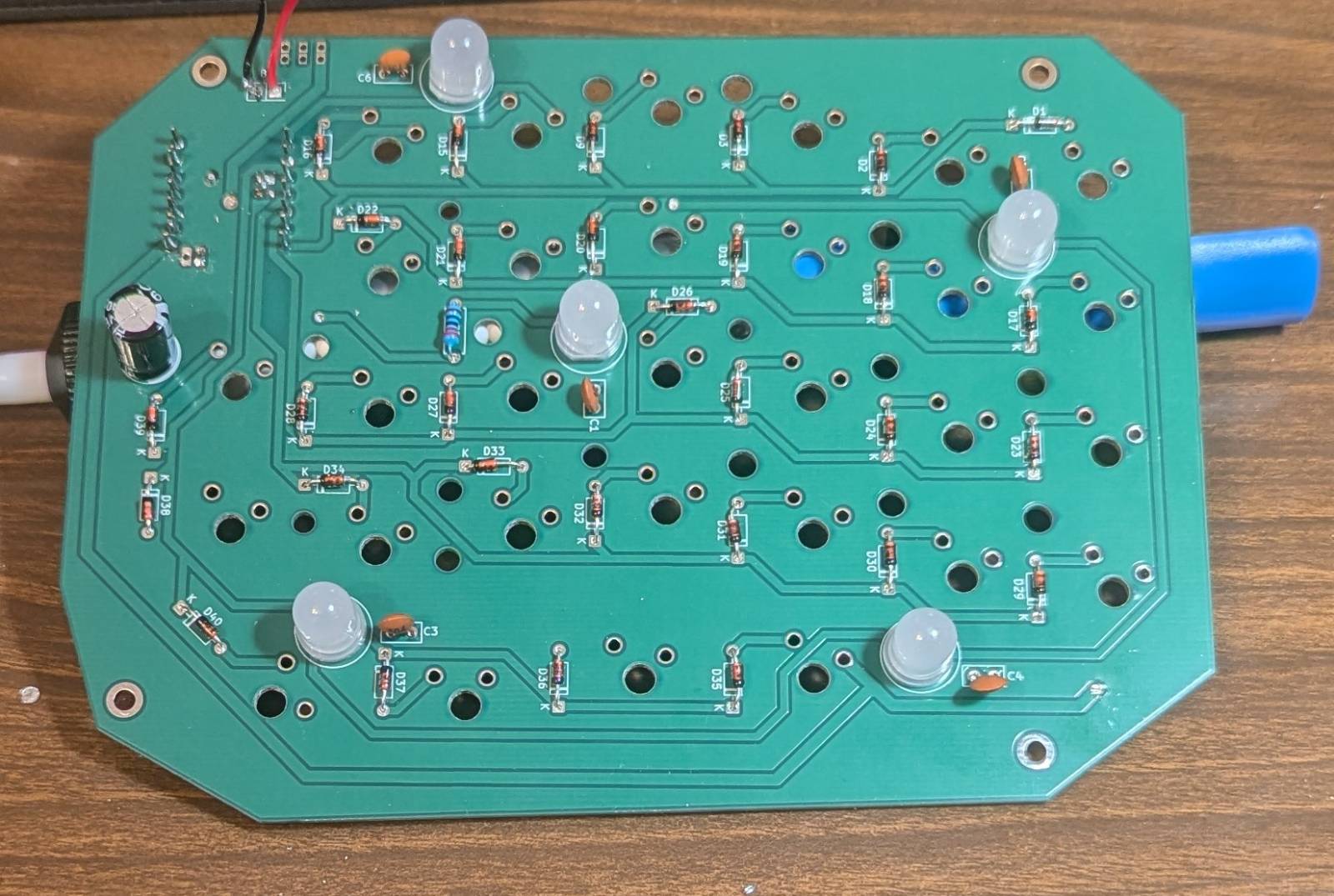
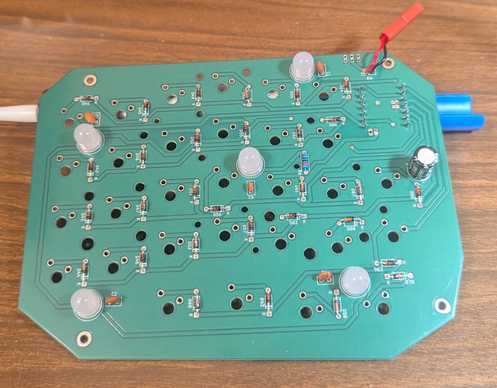
| Qty | Value | Footprint | References |
|---|---|---|---|
| 30 | 1N4148 | Diode_THT:D_DO-35_SOD27_P7.62mm_Horizontal | D1, D2, D15, D16, D17, D18, D19, D20, D21, D22, D23, D24, D25, D26, D27, D28 +14 |
| 30 | SW_Push | Button_Switch_Keyboard:SW_Cherry_MX_1.00u_Plate | SW1, SW2, SW10, SW11, SW12, SW13, SW14, SW15, SW16, SW17, SW18, SW19, SW20, SW21, SW22, SW23 +14 |
| 5 | 100n | Capacitor_THT:C_Disc_D5.0mm_W2.5mm_P2.50mm | C1, C3, C4, C5, C6 |
| 5 | ~ | nrf52840:PL9823-F8 | U2, U3, U4, U5, U6 |
| 4 | MountingHole | MountingHole:MountingHole_2.7mm_M2.5_DIN965_Pad | H1, H2, H3, H4 |
| 1 | 100 | Resistor_THT:R_Axial_DIN0207_L6.3mm_D2.5mm_P7.62mm_Horizontal | R7 |
| 1 | 470u | Capacitor_THT:CP_Radial_D8.0mm_P3.50mm | C2 |
| 1 | Li-Pol Battery | Connector_PinSocket_2.54mm:PinSocket_2x01_P2.54mm_Vertical | B1 |
| 1 | SS22T25 | nrf52840:slider | SW_POW1 |
| 1 | XIAO-nRF52840-DIP_SMD | nrf52840:XIAO-nRF52840-DIP_SMD | U1 |
It measures 149.5 × 111.4 mm and has 2 copper layers, 1.6 mm thick.
79 parts. The full list of its parts is on this page, with links to each part's symbol and footprint where PCBKit's library has them.
From the WGRL/split-keyboard repository on GitHub, at the commit this page was made from: the board is hardware/left_side/left_side.kicad_pcb and its schematic hardware/left_side/left_side.kicad_sch. PCBKit opens the board in the browser, with nothing to install.
Its repository publishes it under the GPL-3.0 licence: you may reuse it on that licence's terms (keep the author's notice, and for a copyleft licence share your changes alike).
espotek-org/Labrador
EspoTek Labrador is a USB device that transforms your PC or smartphone into a fully-featured electronics lab. This repo holds all of the source code!

hackclub/OnBoard
💡 Join 1,000 teenagers and make your first PCB with a $100 grant!

ElectronicCats/Minino
Minino is an original multiprotocol and multiband board made for sniffing, communicating, and attacking IoT devices. It was designed as a mini Cat that integrates the powerful ESP32C6, GPS, microSD and OLED.

strayer/taira-keyboard
A wireless low-profile split mechanical keyboard with 66 keys inspired by the ErgoDash and Corne Chocolate


cnlohr/cnhardware
My dumping grounds for all my kicad projects and random hardware bringup.
