2 layers52.3 × 10.5 mm
StackLink
gusmanb/logicanalyzer
24 channel, 100Msps logic analyzer hardware and software
29 parts5.1kGPL-3.0
 wetzii/Hackpad1
This is my first real Try for HackClub Blueprint challange
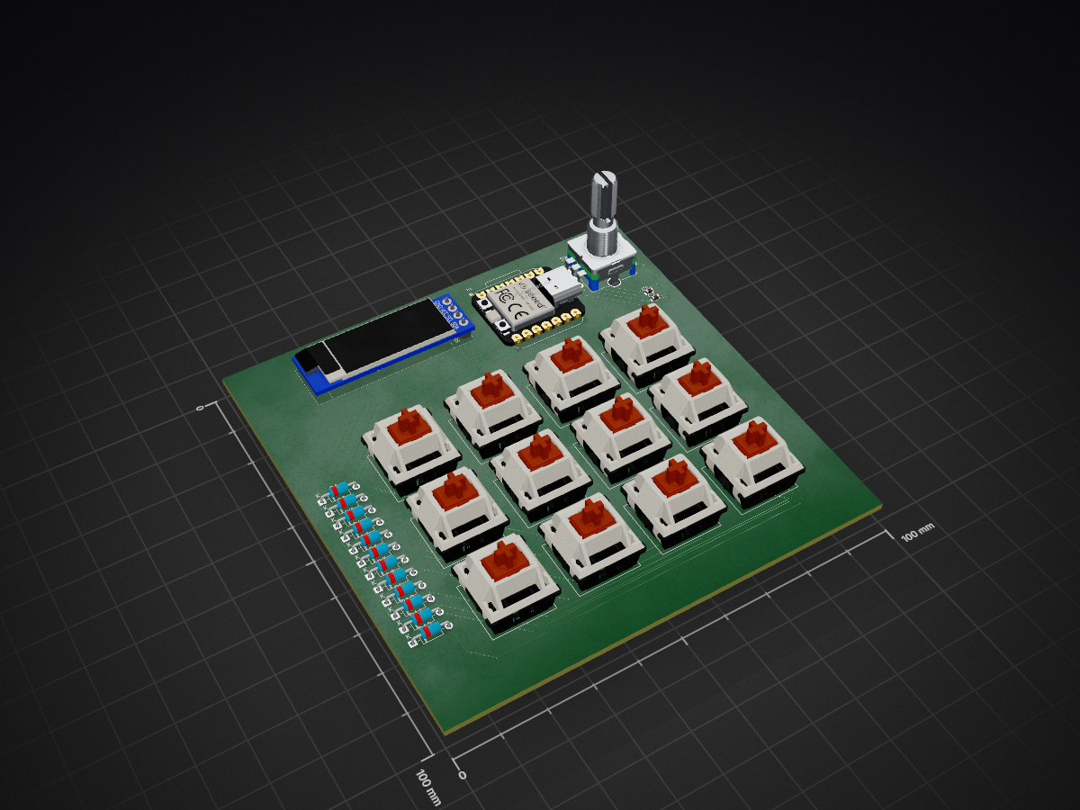
Blueprint PCB AW V3 is an open-source printed circuit board by wetzii, from the wetzii/Hackpad repository on GitHub, published under the MIT licence. It is a 2-layer board of 100 × 100 mm with 29 parts on 30 nets, routed with 177 tracks and 0 vias.
Its parts include 13 switches, 12 diodes, 2 capacitors, 1 IC and 1 connector. It belongs with the RP2040 boards of this library.
This is my first real try for the Hack Club Blueprint challenge! I wanted to build something functional and learn the full process from PCB design to 3D modeling. This project was guided by the Hackpad Guide
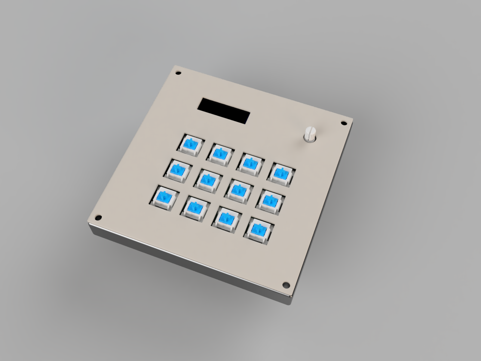
My goal was to create a clean and simple macro pad with the following features:
To build this, I am using the following components:
I will use it as a custom Small Numpad. The OLED screen will act as a system monitor or a simple clock to keep track of time while working or just to watch cool animations.
I designed the circuit to be reliable and easy to solder. It uses a row-column matrix to handle all 16 switches with the limited pins of the XIAO.
Important to know The Rotary Encoder Switch just works to mute and unmute the Capacitor just there as backup! I would work without the Capacitors but for me its okay.
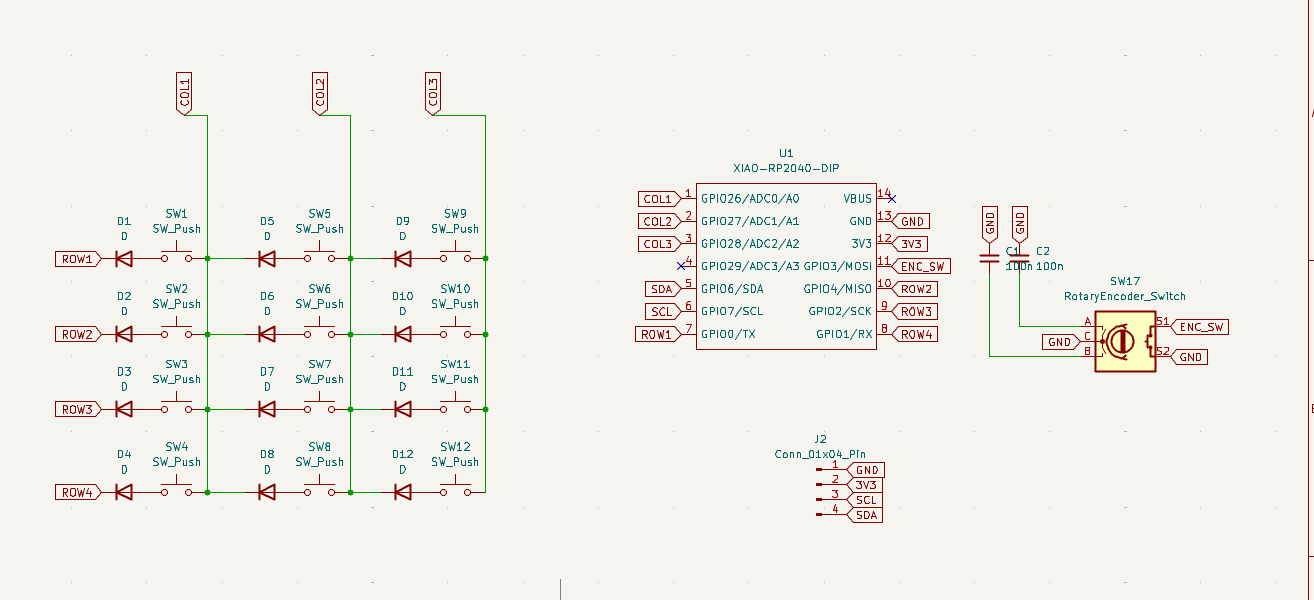
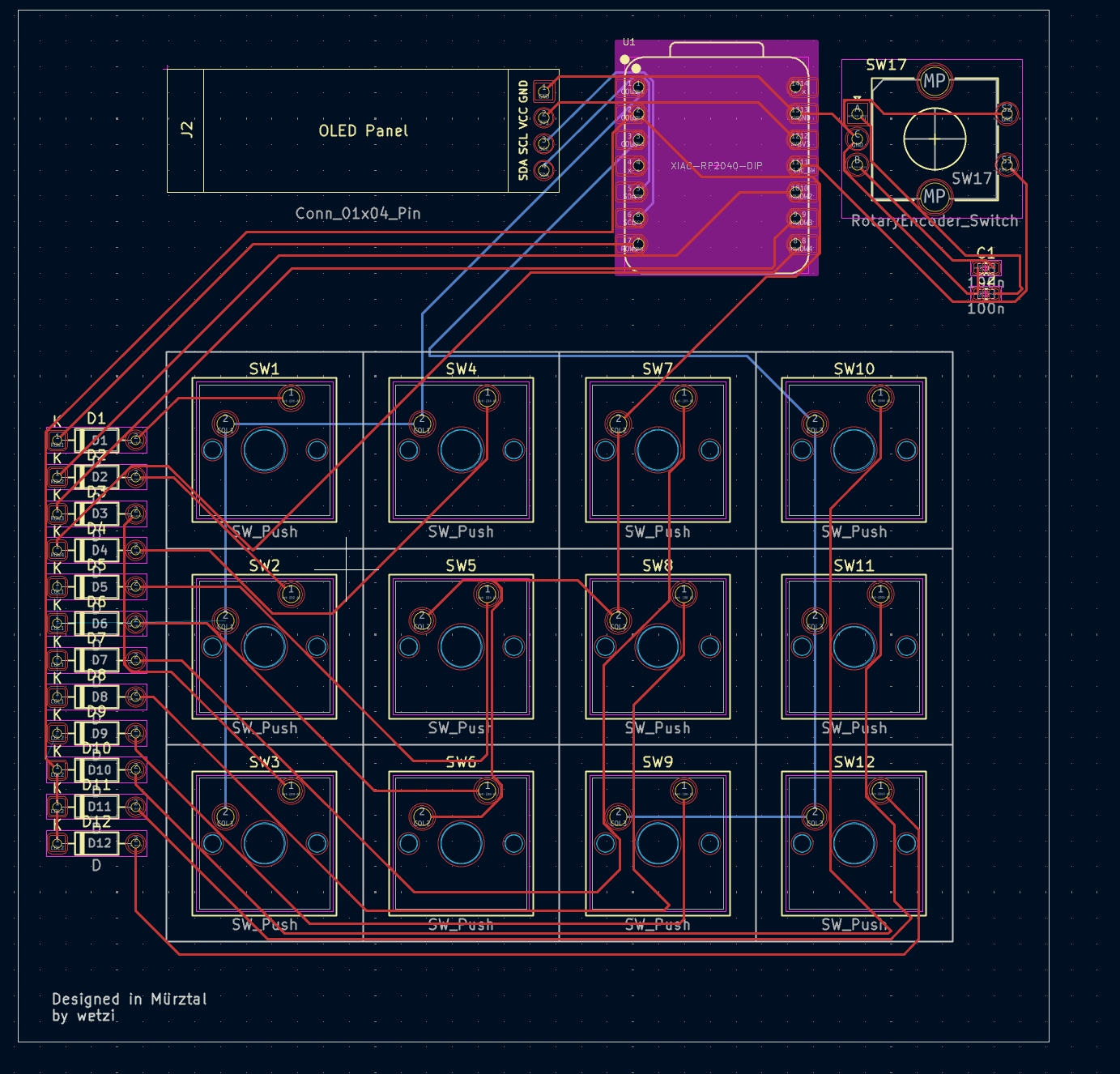
This is the heart of the Hackpad. I routed everything carefully to fit the 4x4 grid and the extra components like the encoder and OLED.
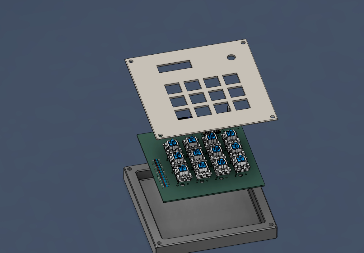
This was my first time 3D modeling anything! I used Fusion 360 for the case design to ensure everything fits perfectly.
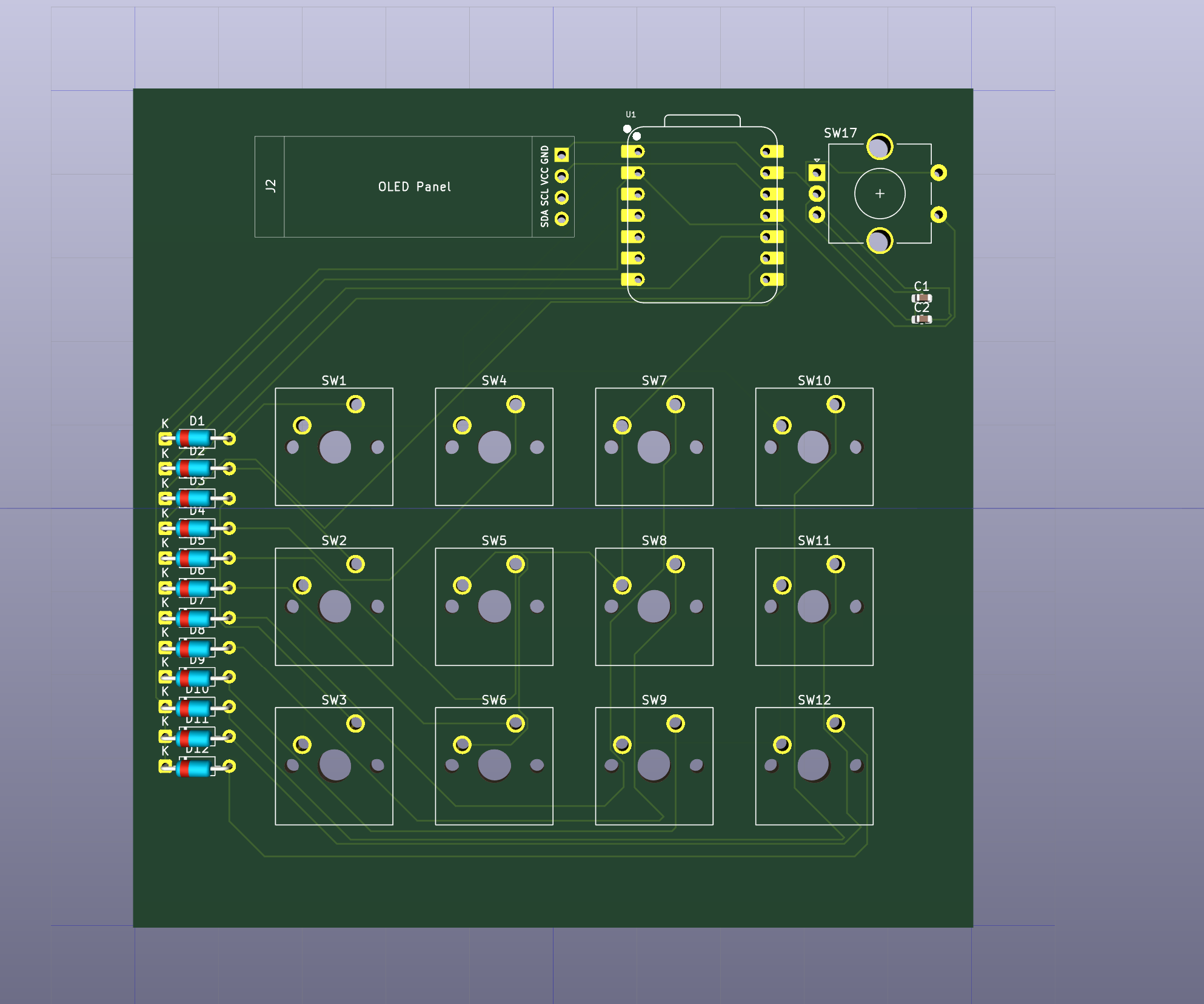
First, I checked the component placement in KiCad's 3D viewer.
I exported the PCB as a .step file and imported it into Fusion 360 to build the case around it.
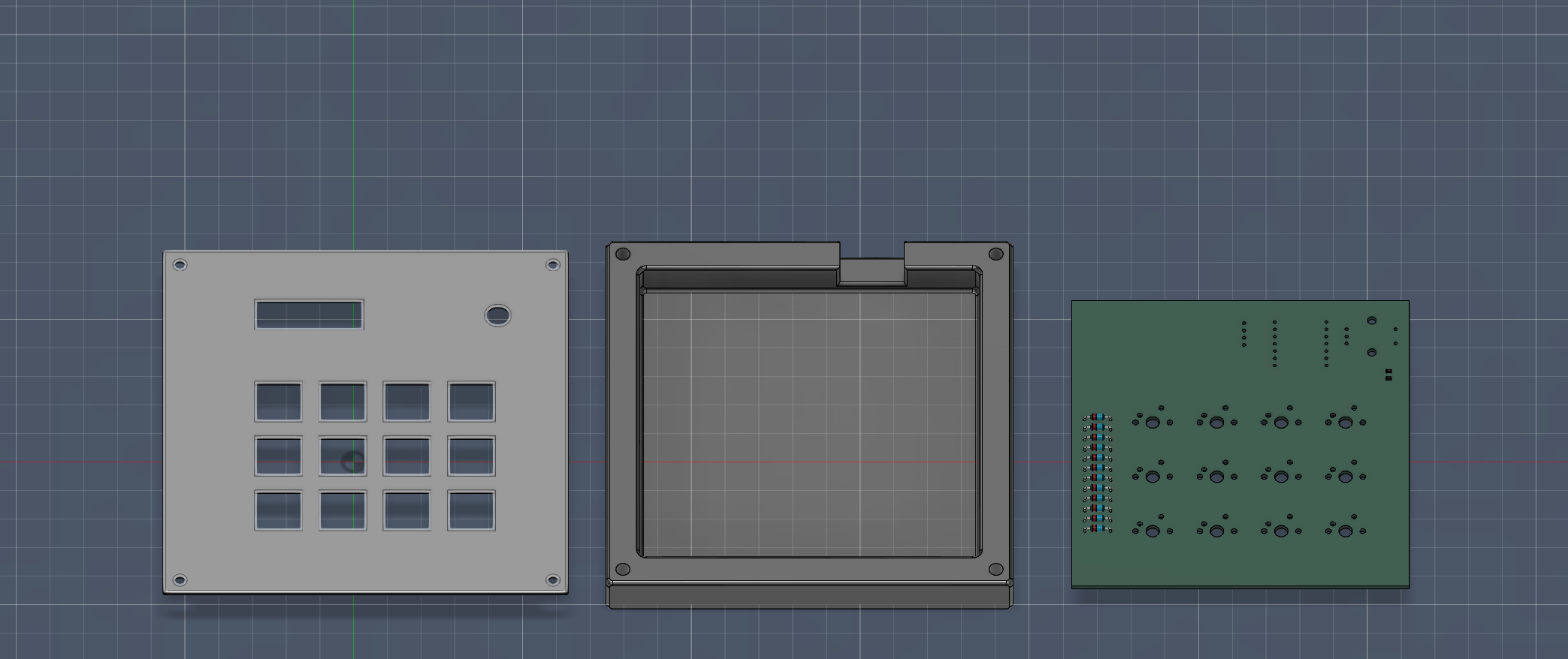
Note: The top plate might need some light sanding for a perfect fit, but I can handle these tolerances during assembly!
The Crash Pad runs on KMK Firmware (CircuitPython).
I am currently learning Python. This firmware was assisted by AI, but my own version is coming soon!
| Qty | Value | Footprint | References |
|---|---|---|---|
| 12 | D | Diode_THT:D_DO-35_SOD27_P7.62mm_Horizontal | D1, D2, D3, D4, D5, D6, D7, D8, D9, D10, D11, D12 |
| 12 | SW_Push | Button_Switch_Keyboard:SW_Cherry_MX_1.00u_PCB | SW1, SW2, SW3, SW4, SW5, SW6, SW7, SW8, SW9, SW10, SW11, SW12 |
| 2 | 100n | Capacitor_SMD:C_0603_1608Metric | C1, C2 |
| 1 | Conn_01x04_Pin | KiCad-SSD1306-0.91-OLED-4pin-128x32.pretty-master:SSD1306-0.91-OLED-4pin-128x32 | J2 |
| 1 | RotaryEncoder_Switch | Rotary_Encoder:RotaryEncoder_Alps_EC11E-Switch_Vertical_H20mm_CircularMountingHoles | SW17 |
| 1 | XIAO-RP2040-DIP | Seeed Studio XIAO Series Library:XIAO-RP2040-DIP | U1 |
It measures 100 × 100 mm and has 2 copper layers, 1.6 mm thick.
29 parts. The full list of its parts is on this page, with links to each part's symbol and footprint where PCBKit's library has them.
From the wetzii/Hackpad repository on GitHub, at the commit this page was made from: the board is PCB/Blueprint_PCB_AW_V3.kicad_pcb and its schematic PCB/Blueprint_PCB_AW_V3.kicad_sch. PCBKit opens the board in the browser, with nothing to install.
Its repository publishes it under the MIT licence: you may reuse it on that licence's terms (keep the author's notice, and for a copyleft licence share your changes alike).
gusmanb/logicanalyzer
24 channel, 100Msps logic analyzer hardware and software

VoronDesign/Voron-Hardware
Cool Hardware designed by the Voron Design group

hoglet67/RGBtoHDMI
Bare-metal Raspberry Pi project that provides pixel-perfect sampling of Retro Computer RGB/YUV video and conversion to HDMI

hackclub/OnBoard
💡 Join 1,000 teenagers and make your first PCB with a $100 grant!

OLIMEX/DIY-LAPTOP
Do It Yourself Open Source Hardware and Software Modular Hacker's Friendly Laptop

UtilitechAS/amsreader-firmware
ESP8266 and ESP32 compatible firmware to read, interpret and publish data to MQTT from smart electrical meters, both DLMS and DSMR is supported

