2 layers100 × 100 mm
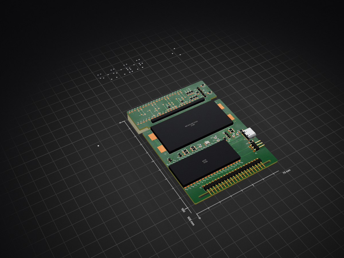
 werediver/clock1
Electronic desktop clock based on Pico/RP2040.
Clock is an open-source printed circuit board by werediver, from the werediver/clock repository on GitHub. It is a 2-layer board of 75 × 105 mm with 80 parts on 90 nets, routed with 425 tracks and 72 vias.
It is built around the LM4040C30FTA, PMV65UNER and PMV75UP, with the ECS-327MVATX-3-CN-TR among its other parts. Its parts include 20 resistors, 7 ICs, 7 transistors, 4 connectors and 1 crystal. It belongs with the lEDs and displays boards and the RP2040 boards of this library.


This Pico-based clock uses a dedicated oscillator for the built-in RP2040 RTC, displays time using seven-segment indicators, features capacitive touch-sensing buttons, and a custom built-in NiMH charging circuit.
The estimated run-time on a single charge is one week (yes, just one week).
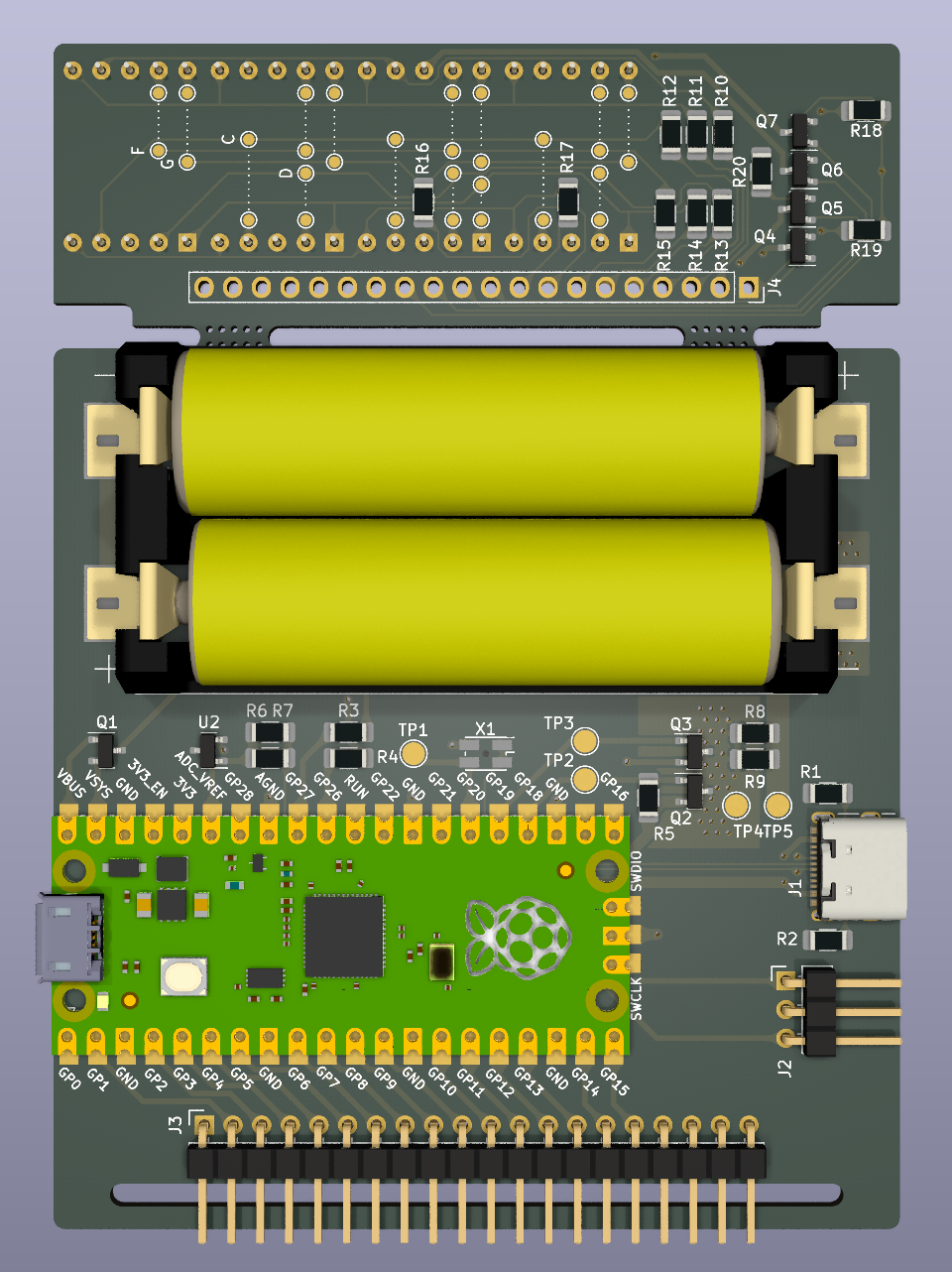
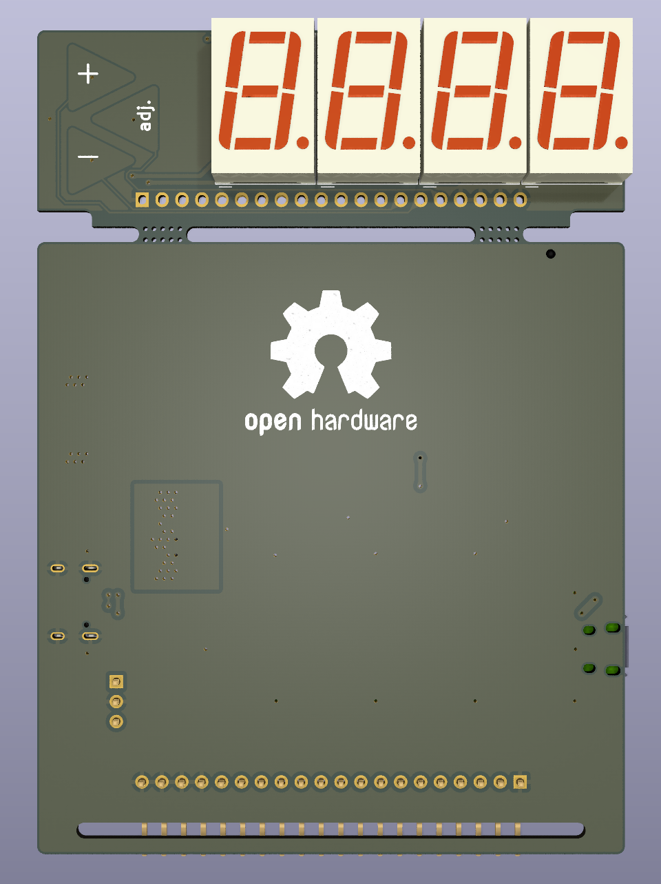
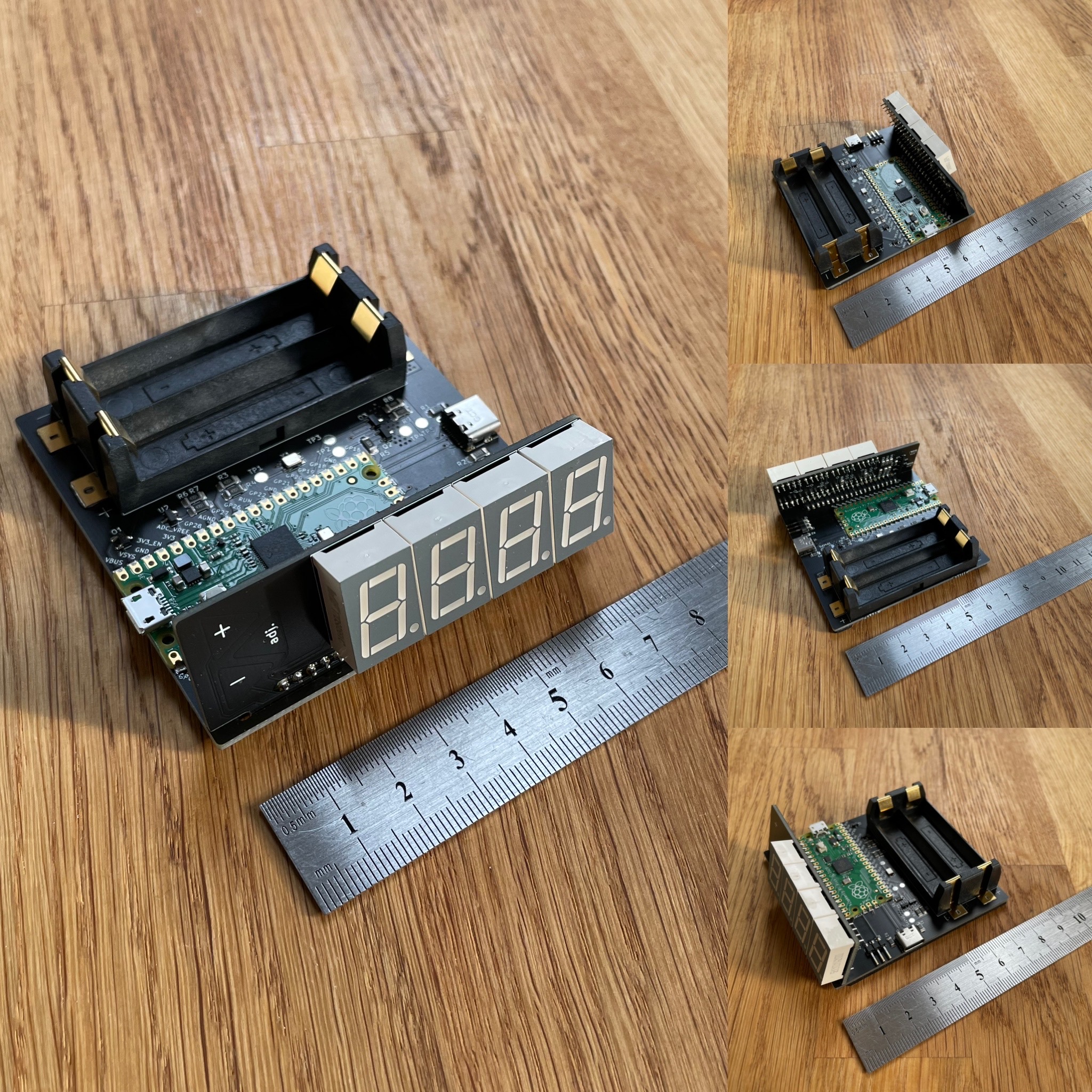
When assembling, refer to the interactive BOM page.
---
title: Charger state machine
---
stateDiagram-v2
    [*] --> Hold
    Hold --> Charge: ext_power && v < HIGH
    Charge --> Charged: d(v) ≤ NDV || is_adc_saturated() || is_timed_out()
    Charged --> Charge: v < HIGH
    Charge --> Hold: !ext_power
Charged --> Hold: !ext_powerv ≥ NiMH_HIGH (1–2h?)| Qty | Value | Footprint | References |
|---|---|---|---|
| 8 | 270 | Resistor_SMD:R_1206_3216Metric_Pad1.30x1.75mm_HandSolder | R10, R11, R12, R13, R14, R15, R16, R17 |
| 8 | F | TestPoint:TestPoint_Pad_D1.0mm | TP_F1, TP_F2, TP_F3, TP_F4, TP_F5, TP_F6, TP_F7, TP_F8 |
| 8 | G | TestPoint:TestPoint_Pad_D1.0mm | TP_G1, TP_G2, TP_G3, TP_G4, TP_G5, TP_G6, TP_G7, TP_G8 |
| 6 | C | TestPoint:TestPoint_Pad_D1.0mm | TP_C1, TP_C2, TP_C3, TP_C6, TP_C7, TP_C8 |
| 6 | D | TestPoint:TestPoint_Pad_D1.0mm | TP_D1, TP_D2, TP_D3, TP_D6, TP_D7, TP_D8 |
| 5 | 4.7k | Resistor_SMD:R_1206_3216Metric_Pad1.30x1.75mm_HandSolder | R3, R4, R5, R6, R7 |
| 5 | PMV65UN | Package_TO_SOT_SMD:SOT-23 | Q3, Q4, Q5, Q6, Q7 |
| 4 | S511SYGWA/S530-E2 | Display_7Segment:D1X8K | U4, U5, U6, U7 |
| 3 | 1M | Resistor_SMD:R_1206_3216Metric_Pad1.30x1.75mm_HandSolder | R18, R19, R20 |
| 2 | 4.7 0.5W | Resistor_SMD:R_1206_3216Metric_Pad1.30x1.75mm_HandSolder | R8, R9 |
| 2 | 5.1k | Resistor_SMD:R_1206_3216Metric_Pad1.30x1.75mm_HandSolder | R1, R2 |
| 2 | E | TestPoint:TestPoint_Pad_D1.0mm | TP_E2, TP_E7 |
| 2 | Mouse Bites | Custom:MouseBites_2x05mm | H1, H2 |
| 2 | PMV75UP | Package_TO_SOT_SMD:SOT-23 | Q1, Q2 |
| 1 | BASE | Connector_PinSocket_2.54mm:PinSocket_1x20_P2.54mm_Vertical | J4 |
| 1 | BATT | TestPoint:TestPoint_Pad_D2.0mm | TP5 |
| 1 | CHRG | TestPoint:TestPoint_Pad_D2.0mm | TP4 |
| 1 | DCHRG EN | TestPoint:TestPoint_Pad_D2.0mm | TP3 |
| 1 | DISP | Connector_PinHeader_2.54mm:PinHeader_1x20_P2.54mm_Horizontal | J3 |
| 1 | ECS-327MVATX-3-C | Oscillator:Oscillator_SMD_EuroQuartz_XO32-4Pin_3.2x2.5mm_HandSoldering | X1 |
| 1 | Keystone 2xAA 1012 | Keystone1012:BatteryHolder_Keystone_1012_2xAA | U3 |
| 1 | LM4040C30 | Package_TO_SOT_SMD:SOT-23 | U2 |
| 1 | Logo_Open_Hardware_Small | Symbol:OSHW-Logo2_24.3x20mm_SilkScreen | SYM1 |
| 1 | Pico | RPi_Pico:RPi_Pico_SMD | U1 |
| 1 | RTC CLK | TestPoint:TestPoint_Pad_D2.0mm | TP1 |
| 1 | SWD | Connector_PinHeader_2.54mm:PinHeader_1x03_P2.54mm_Horizontal | J2 |
| 1 | TCH A | Custom:TouchPad | TP6 |
| 1 | TCH B | Custom:TouchPad | TP7 |
| 1 | TCH C | Custom:TouchPad | TP8 |
| 1 | USB_C_Receptacle_USB2.0 | Connector_USB:USB_C_Receptacle_GCT_USB4105-xx-A_16P_TopMnt_Horizontal | J1 |
| 1 | ~{CHRG EN} | TestPoint:TestPoint_Pad_D2.0mm | TP2 |
It measures 75 × 105 mm and has 2 copper layers, 1.6 mm thick.
80 parts, built around the LM4040C30FTA, PMV65UNER, PMV75UP and ECS-327MVATX-3-CN-TR. The full list of its parts is on this page, with links to each part's symbol and footprint where PCBKit's library has them.
From the werediver/clock repository on GitHub, at the commit this page was made from: the board is KiCad/Clock.kicad_pcb and its schematic KiCad/Clock.kicad_sch. PCBKit opens the board in the browser, with nothing to install.
Its repository states no licence, so its author keeps all rights: ask werediver before reusing the design.


bluekeyes/pico-12vrgb-hid-controller
4-pin RGB controller using the Pi Pico and USB HID

shabaz123/Vectorscope_GuyFawkes
A reimplementation of the Vectorscope from https://github.com/Hack-a-Day/Vectorscope


oresat/oresat-adcs-hardware
Controller PCB for OreSat reaction wheels, magnetorquers, IMU, and magnetometers