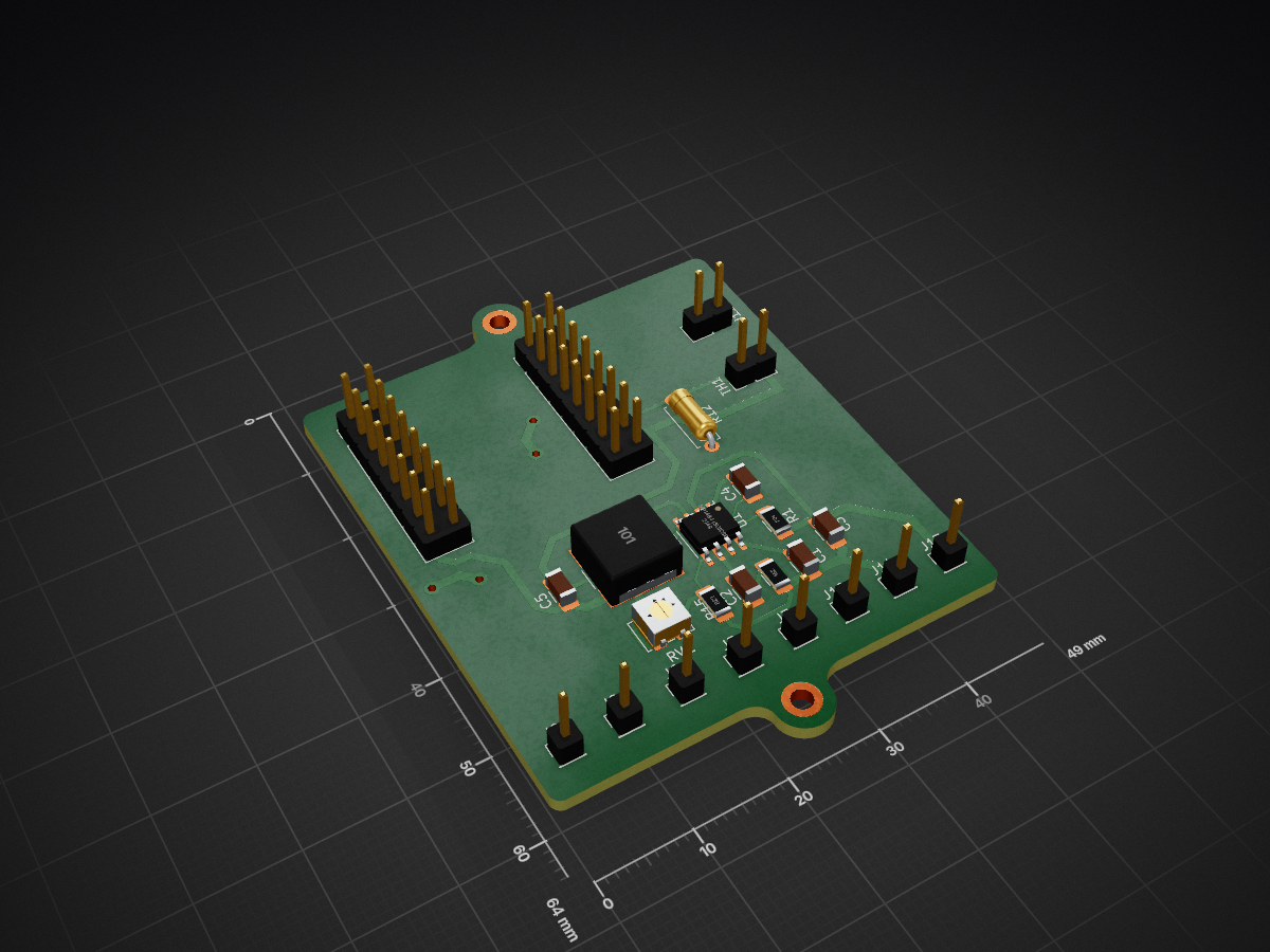
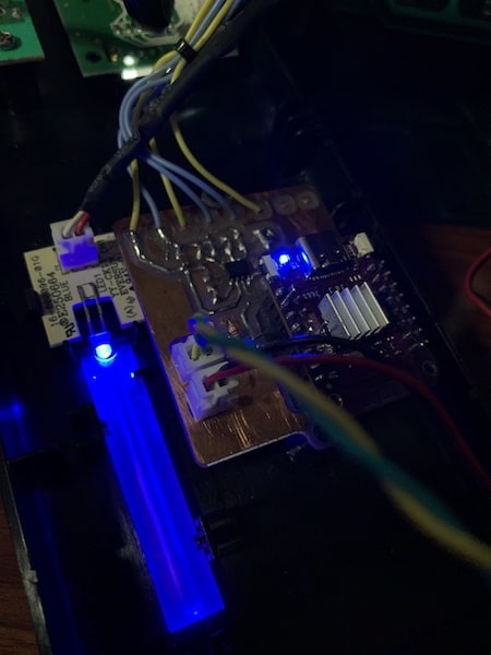
TinyUPS is an open-source printed circuit board by way5, from the way5/tinyUPS repository on GitHub, published under the GPL-3.0 licence. It is a 2-layer board of 49 × 64 mm with 45 parts on 47 nets, routed with 282 tracks and 4 vias.
It is built around the BSS138 and IRLML2502. Its parts include 15 resistors, 11 connectors, 6 transistors, 5 capacitors and 2 diodes. It belongs with the power boards and the ESP32 boards of this library.
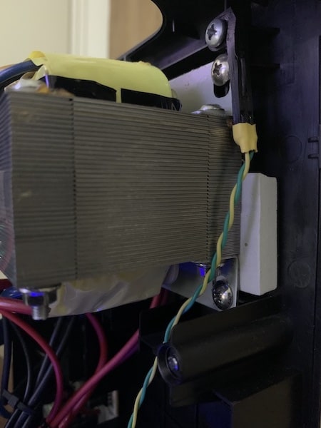
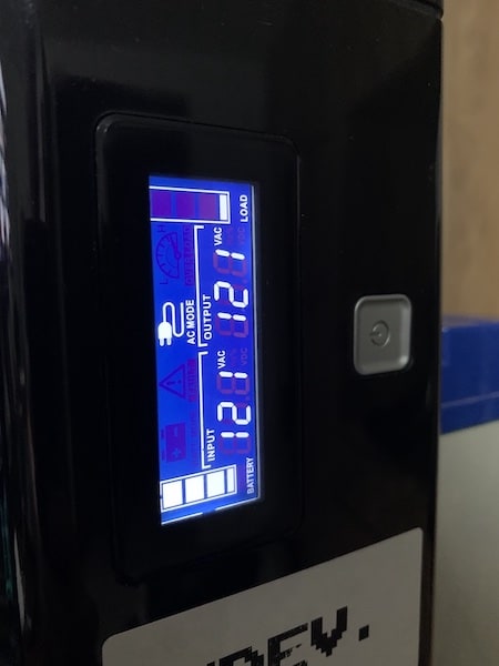
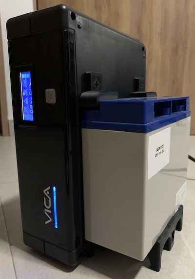
tinyUPS is the way to extend functionality of an Uninterruptible Power Supply (UPS)/power inverters.
It provides onboard SNMP server, temperature control and a Control Panel (CP), just like on an enterprise systems.
The project is now on beta test stage, however it shows very stable results during months 24/7. If you'll decide to modify your own UPS it's at your own risk.
This project requires advanced skills in electronics. It's not a plug-n-play device. ;)
Follow the standard precautions! Uninterruptible Power Supply (UPS) is a potentially dangerous device as it contains electric parts under high voltage.
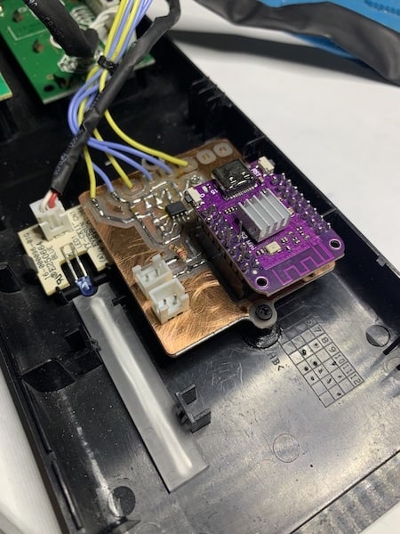
tinyUPS is originally based on WEMOS S2 mini board. However, very likely it would work on another ESP32 boards with minor changes in firmware.
All the configuration you may need is in platformio.ini and the UPS driver header file. If the communication interface of a particular UPS is not SPI, you need to create a new UPS driver and to change the PCB as well.
If you've created a new driver please share it by creating merge request or attaching it in discussions.
- PCB [blocked]
The current PCB is designed for DIY via CAM method. If you want it printed profesionally, you may need to redesign the PCB.
Since the most of the UPS controllers have 5V data bus, we need a level shifter to be able to communicate with them and a small step-down PSU for ESP32.
Bill of materials. Instead of the BSS138 mosfets could be used any compatible type, ex.: IRLML2502.
If you'll be using S2 mini board you need to desolder built-in LDO IC (ME6211C33) since power will be supplied directly to 3.3V pin. It's possible to keep the LDO but you will not be able to use serial port for firmware upload and debugging. See WEMOS S2 mini schematics.
The example driver is for a built in SPI LCD display, for a particular manufacturer and model.
You'll probably have the very different device and may be even without any LCD display, so you'd need to figure out how to speak with the controller. This part is DIY. Feel free to call for help in Discussions.
- Web UI [blocked]
UI translations are available in ./web/lang directory. You can add new translation or remove existing if you wish by editing the header of i18n.js script. Variable i18nlang contains the list of available locales to be built-in, where element 0 of the array is also a fallback (used by default) locale. Remove unnecessary locales from i18nlang to save space on file system partition.
The package manager is yarn so if you're not familiar with it continue with the folowing to build the UI:
bash
yarn build:prod
that's all you need to prepare the FS partition to upload. Use Upload Filesystem Image command from PlatformIO project tasks or:
bash
platformio run --target uploadfs [--environment [your_env]]
+ BUILD [blocked]
- CONFIGURATION [blocked]
All sigificant parameters for your setup are inside configrure.json file. If you're adding a new parameter you'd need to run Rebuild Intellisense Index in PlatformIO in order to have your parameter set and available.
PARAMETER
DESCRIPTION
system_log_size
Size of the system log file (in bytes)
snmp_log_size
Size of the SNMP server log file (in bytes)
mtemp_log_size
Size of the temperature management log (in bytes)
mdata_log_size
Size of the log of monitored events (in bytes)
ups_rated_input_voltage
Nominal input voltage value (V)
ups_rated_input_freq
Nominal input frequency (Hz)
ups_rated_low_input_voltage_threshold
Nominal low threshold of the input voltage (V)
ups_rated_high_input_voltage_threshold
Nominal hight threshold for input voltage (V)
ups_rated_output_voltage
Nominal output voltage (V)
ups_rated_output_freq
Nominal output frequency (Hz)
battery_rated_charge_capacity_ah
Nominal UPS battery capacity (Ah)
ups_rated_battery_amps_max
Nominal UPS battery current (Amps)
wifi_reconnect_method
WiFi reconnection method (see below)
wifi_discovered_length
Max. length of the data array of discovered APs
- WiFi CONNECTION STRATEGIES [blocked]
If tinyUPS has lost connection with AP you may wish it to fallback to AP mode (tinyUPS.01.XXXX network name) or it may keep trying to reconnect till the source network is available.
You can choose the desired behavior (see wifi_reconnect_method parameter) before to compile firmware.
METHOD_ID
DESCRIPTION
1
If the configuration data is available, tinyUPS intents to connect to the specified AP. If the connection is not succeeded it starts AP. If connection is lost the device tryes to reconnect once (10 sec interval). If connection is not succeeded it starts AP and remains in this mode until restart.
2 [D]
If tinyUPS has lost connection with source network it tryes to reconnect once. If connection is not succeeded it starts AP and periodically scans WiFi networks. If the source network has found, the device intents to reconnect. Unless the connection is succeeded it remains in AP mode.
3
Once the device has lost connection to AP it continuously tryes to reconnect to the source network. The WiFi mode remains STA.
4
Rely on built-in functionality of setAutoReconnect(). tinyUPS will remain in STA mode and be seeking for the source AP.
[D] - the default method
+ SETUP [blocked]
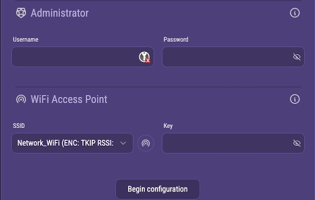
When you first run tinyUPS, it boots up in AP mode. Look for tinyUPS.01.XXXX WiFi network. Default network password (config.apkey) could be changed in helpers.h. Once connected the configuration is available on 192.168.4.1.
When setup is completed tinyUPS restarts, expecting an automatically assigned IP.
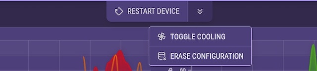
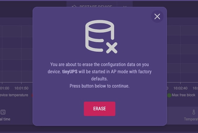
You are able to restart the device or reset configuration data to defaults using Control Panel -> Service Menu:
and then continue with confirmation:
+ CONTROL PANEL [blocked]
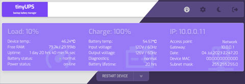
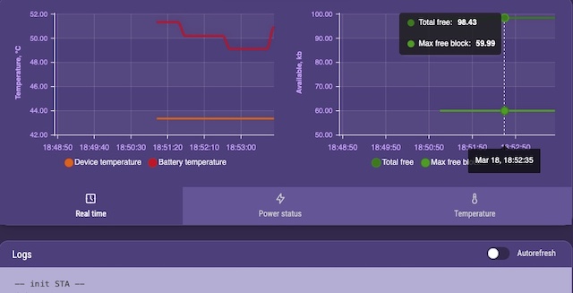
The UI is pretty simple and displays most of the real-time parameters. There are multiple self explanatory graphical representations for the collected data.
After successful setup it is highly recommended to change the AP key and generate the device serial number. Both options and corresponding controls you can find in Settings -> Security tab and SNMP tab respectively.
+ DEVELOPMENT [blocked]
- DRIVERS [blocked]
There are the following functions that must be implemented by every UPS driver: upsDriverInit, upsDriverLoop, upsDriverDeinit.
You may also wish to look at the driver for thermistor (currently this is 1k M52A), it may need some changes. Depends on which thermistor you'll be using.
- DEBUG [blocked]
Serial monitor is used to perform the most of the tasks and to solve issues. Once you've connected use ? to list available commands.
It measures 49 × 64 mm and has 2 copper layers, 1.6 mm thick.
What parts does the TinyUPS use?
45 parts, built around the BSS138 and IRLML2502. The full list of its parts is on this page, with links to each part's symbol and footprint where PCBKit's library has them.
Where can I download the TinyUPS KiCad files?
From the way5/tinyUPS repository on GitHub, at the commit this page was made from: the board is schematics/CAM/tinyUPS.kicad_pcb and its schematic schematics/CAM/tinyUPS.kicad_sch. PCBKit opens the board in the browser, with nothing to install.
Can I use the TinyUPS design in my own project?
Its repository publishes it under the GPL-3.0 licence: you may reuse it on that licence's terms (keep the author's notice, and for a copyleft licence share your changes alike).
High efficient PV charging of HV-Battery with 650V-GaN power stage. A second GaN-power stage is used as a Single-Phase inverter, which enables high efficient self-consumption.