
2 layers111.9 × 39.5 mm

 wang-eric-c/6DOF-Robotic-Arm
Mechanical: Complete, PCB: Version 2 in progress, Firmware: Prototyping done, final in progress, Software/Sim: In progress
ArmPCBv1 is an open-source printed circuit board by wang-eric-c, from the wang-eric-c/6DOF-Robotic-Arm repository on GitHub. It is a 4-layer board of 84.2 × 64.6 mm with 38 parts on 47 nets, routed with 230 tracks and 40 vias.
It is built around the STM32C092KBT6. Its parts include 11 capacitors, 7 connectors, 5 resistors, 5 ICs and 2 diodes. It belongs with the STM32 boards of this library.
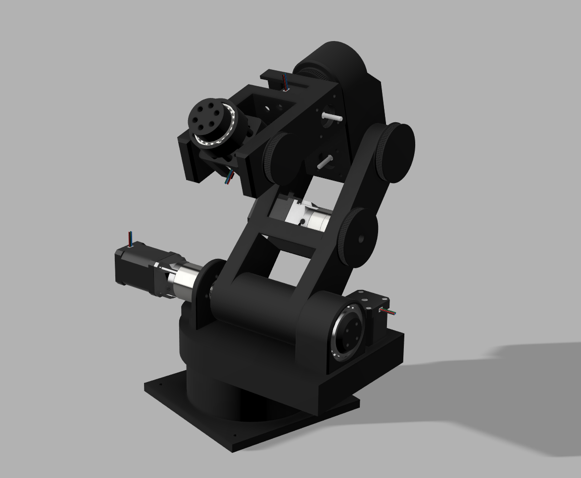
A 6 degree-of-freedom robotic arm mechanical design: custom CAN bus driver electronics, and ESP32 firmware.
| Subsystem | State |
|---|---|
| Mechanical (STEP / STL) | ✅ Complete |
| PCB v1 (CAN + daisy-chained power) | ✅ Designed |
| PCB v2 (compact single-board) | 🚧 In progress |
| Firmware (ESP32) | 🚧 Joint test interface working |
| URDF / simulation | 📦 Separate repo — see below |
| Kinematics / motion planning | In progress |
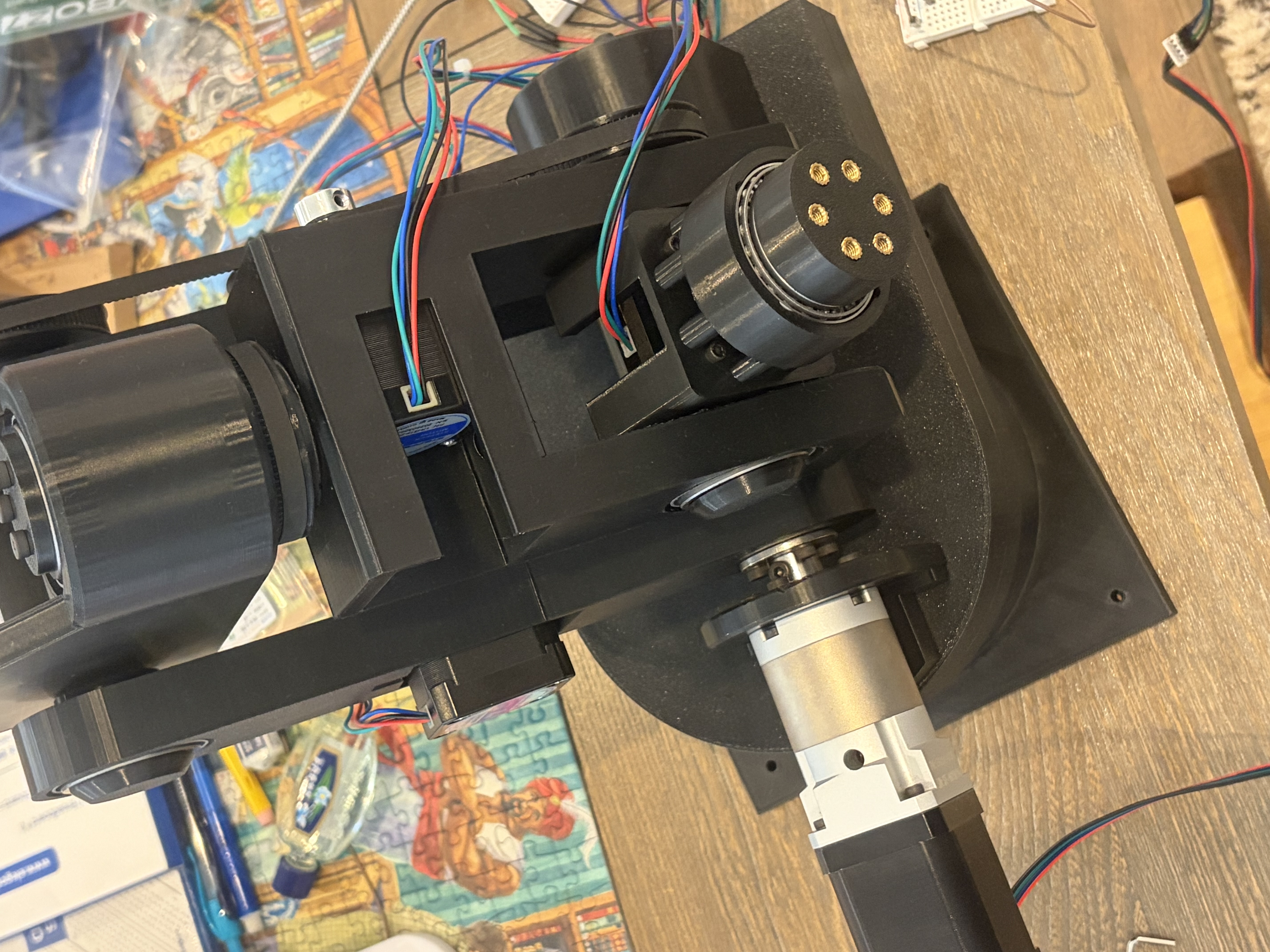
Short clips from prototyping. These are modular, single-joint movements recorded during bring-up.
Full CAD is complete and released.
TODO: print settings, material
One driver board per joint, linked over a CAN bus with daisy-chained power, so each joint only needs a single connection to its neighbor rather than a run back to a central controller. This keeps the harness inside the arm minimal.
Designed in KiCad.
A second revision is in progress that consolidates the design onto one more compact board.
TODO: schematic PDF, connector pinout, power requirements, motor/driver part numbers.
ESP32 firmware for bench-testing individual joints through a web interface. The board hosts a page that exposes per-joint controls, so joints can be jogged and characterized without writing host-side code.
This is test/bring-up firmware — not a motion controller.
TODO: flashing instructions, pin mapping, network setup, toolchain.
The robot description lives in a separate repository:
| Qty | Value | Footprint | References |
|---|---|---|---|
| 4 | 100 nF | Capacitor_SMD:C_0402_1005Metric | C4, C5, C7, C10 |
| 3 | M4 | MountingHole:MountingHole_4.3mm_M4 | H1, H2, H3 |
| 2 | 10 pF | Capacitor_SMD:C_0402_1005Metric | C8, C9 |
| 2 | 100 uF | Capacitor_THT:CP_Radial_D8.0mm_P5.00mm | C3, C11 |
| 2 | 10k | Resistor_SMD:R_0402_1005Metric | R2, R4 |
| 1 | 100 kOhm | Resistor_SMD:R_0402_1005Metric | R1 |
| 1 | 100nF | Capacitor_SMD:C_0402_1005Metric | C1 |
| 1 | 10A | Fuse:Fuse_1206_3216Metric | F1 |
| 1 | 10uF | Capacitor_SMD:C_0805_2012Metric | C2 |
| 1 | 330 Ohm | Resistor_SMD:R_0402_1005Metric | R3 |
| 1 | 330 uF | Capacitor_THT:CP_Radial_D8.0mm_P5.00mm | C6 |
| 1 | 8 MHz | armpcb:8MHz Osc | Y1 |
| 1 | A4988_STEPPER_MOTOR_DRIVER_CARRIER_BLACK | armpcb:Stepper Driver | U4 |
| 1 | Buck Inductor | armpcb:Buck Inductor | L1 |
| 1 | Buck diode | armpcb:Buck Diode | CR1 |
| 1 | CAN Diode | armpcb:CAN Diode | U5 |
| 1 | CAN Transceiver | armpcb:CAN Transceiver | U1 |
| 1 | CAN_IN | Connector_PinHeader_2.54mm:PinHeader_1x02_P2.54mm_Vertical | J6 |
| 1 | CAN_OUT | Connector_PinHeader_2.54mm:PinHeader_1x02_P2.54mm_Vertical | J7 |
| 1 | Conn_01x05 | Connector_PinHeader_2.54mm:PinHeader_1x05_P2.54mm_Vertical | J4 |
| 1 | D_Zener | Diode_SMD:D_SOD-123 | D1 |
| 1 | GPIO Board | Connector_PinHeader_2.54mm:PinHeader_1x13_P2.54mm_Vertical | J3 |
| 1 | Green LED | LED_SMD:LED_0603_1608Metric | D2 |
| 1 | Logic Buck | armpcb:Logic Buck | U2 |
| 1 | MOSFET | armpcb:MOSFET | Q1 |
| 1 | Motor Header | Connector_PinHeader_2.54mm:PinHeader_1x04_P2.54mm_Vertical | J5 |
| 1 | Optional 120 Ohm | Resistor_SMD:R_0603_1608Metric | R5 |
| 1 | STM32C092KBT6 | armpcb:New MCU | U3 |
| 1 | XT30 - F | Connector_AMASS:AMASS_XT30PW-F_1x02_P2.50mm_Horizontal | J1 |
| 1 | XT30 - M | Connector_AMASS:AMASS_XT30PW-M_1x02_P2.50mm_Horizontal | J2 |

caketetu/SPM-STMTB-V1
SPM-STMTBを使用した低電圧バイポーラステッピングモータードライバ(Low Voltage Stepping motor Driver) ドライバICはToshibaのTC78S600FTGを使用。\…


Hanqaqa/Easyduino
Easily dive into different PCB KiCad designs of the most popular microcontroller devboards

murexrobotics/electrical
Highly integrated electronics design and printed circuit boards (PCBs) for the MATE ROV Competition. Attempt the impossible.


magnusnordlander/smart-lcc
A smarter LCC for the Lelit Bianca V2, with Wi-Fi and stuff.
It measures 84.2 × 64.6 mm and has 4 copper layers, 1.6 mm thick.
38 parts, built around the STM32C092KBT6. The full list of its parts is on this page, with links to each part's symbol and footprint where PCBKit's library has them.
From the wang-eric-c/6DOF-Robotic-Arm repository on GitHub, at the commit this page was made from: the board is ArmPCBv1/ArmPCBv1.kicad_pcb and its schematic ArmPCBv1/ArmPCBv1.kicad_sch. PCBKit opens the board in the browser, with nothing to install.
Its repository states no licence, so its author keeps all rights: ask wang-eric-c before reusing the design.