Skip to the content
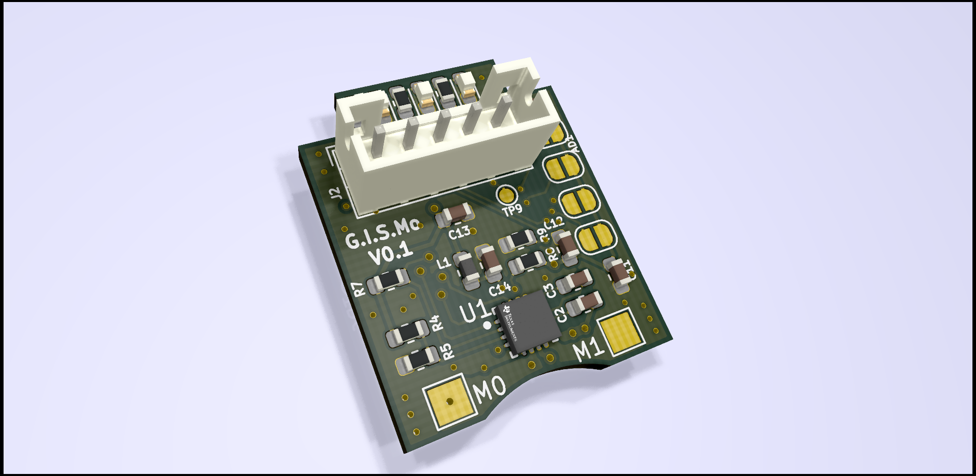
2 layers47.6 × 36.8 mmSmartServo, the printed circuit board in 3D

SmartServo

wandrade/GISMo6

Greatly Inteligent Servo Motor (G.I.S.Mo) - Adapt a MG995 or similar servo to a propper smart servo with current sensing and cool control methods (cause the ones that are cheap are sh**, and the other ones too)

Size
47.6 × 36.8 mm
Copper layers
2
Thickness
1.6 mm
Parts
47
Nets
40
Pads
161
Tracks, vias
297, 126
Pours
2
Routed
Yes
KiCad
KiCad 5 (file 20171130)
Created
5 Sep 2020
Updated
17 Sep 2024

Overview

SmartServo is an open-source printed circuit board by wandrade, from the wandrade/GISMo repository on GitHub, published under the GPL-3.0 licence. It is a 2-layer board of 47.6 × 36.8 mm with 47 parts on 40 nets, routed with 297 tracks and 126 vias.

Its parts include 14 capacitors, 9 resistors, 6 connectors, 3 diodes and 2 ICs. It belongs with the robots and motor control boards and the STM32 boards of this library.

README

README.md

G.I.S.Mo

After a long search, I have failed to find a servo motor that does everything I need for my projects that is also cheap(ish) and fully programmable (say no to closed source stuff whenever you can).

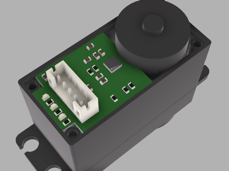
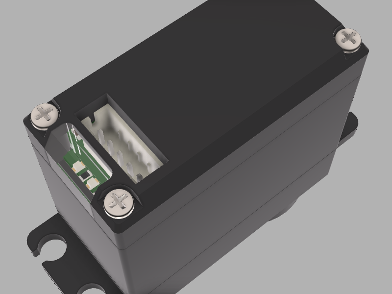
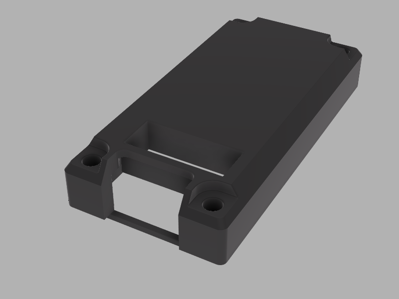
Well, thus was born the idea of GISMo (Greatly Inteligent Servo Motor). This project aims to develop a board that can be used to replace the vanilla servo driver boards that comes with cheaper ones such as MG995 and MG996R, giving it more power and making it more usefull for distributed controll projects:

Wishlist:

  • Embedded MCU (STM32F302 powered!)
  • Current sensing (for torque controll and power management features)
  • I2C interface (or if you please, just change a bit the circuit to use whatever interface you want)
  • Programable LED's (because they are cool)
  • Absolute magnetic encoder (at least 12bits)
  • Free range of movement (180 degrees is just not enough)
  • Control:
    • Simple position PID loop
    • MISO controller for speed and position simultaniously (Probably a state space controller)
    • Torque controll loop
    • Trapezoidal position curve following
  • Configurable parameters
    • Speed/Position/Current limit
    • Controller mode
    • Configurable break zone (turn on break when position reaches its demand and settles)
    • Multiturn counter
    • Controller gains (PID and state space gain matrix)
  • ROS2 Interface node:
    • Hot plug I2C device detection
    • Configuration via YAML and ROS Param
    • up to 16 Individually addressed servos

Organization

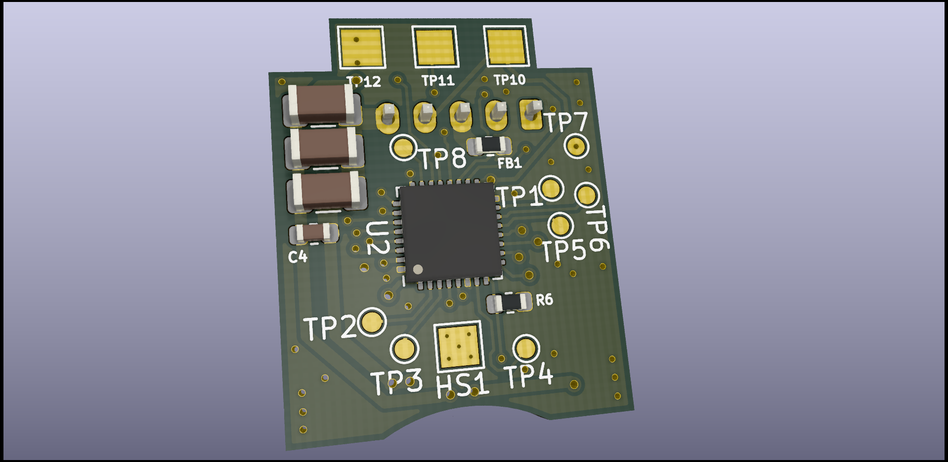
The project contains 3 main blocks: first is the hardware, using KiCad, in the Hardware folder you will find 2 subfolders, one for the dev board, which is a big version of the board with some more stuff to facilitate firmware development and debugging, and a second one that contains the GISMo board that actually fits in the servo (to be made). Then we have the Firmware with two other bits, the CubeMX project so we have everything neatly initialized in our MCU, and the actual firmware and its libs.

Version History

Now this is a bit tricky. I have 3 things to version and no interest in havving 3 different repos for them at all, so ill trake and make it sensible.

Each sub-thing will have its own sub-version, and once I have a combination of the 3 of them that kind of works, I will merge it into the master branch and tag it with a overall version of the repo (if that makes sense).

Firmware

--

GISMo Board

  • 0.0.1 - Copy of dev board with a few changes to reduce space usage
    • Only one I2C/Power plug
    • Replaced Address header pins by solder jumpers
    • Motor and PWM sensor connectors replaced with solder pads
    • Included a heat sink pad under the motor driver
    • Removed Crystal and oscilator
    • Reduced LED packages
    • Removed Debug connector
    • Removed reset button

Development Board

This board is meant for circuit testing and ease of debugging.
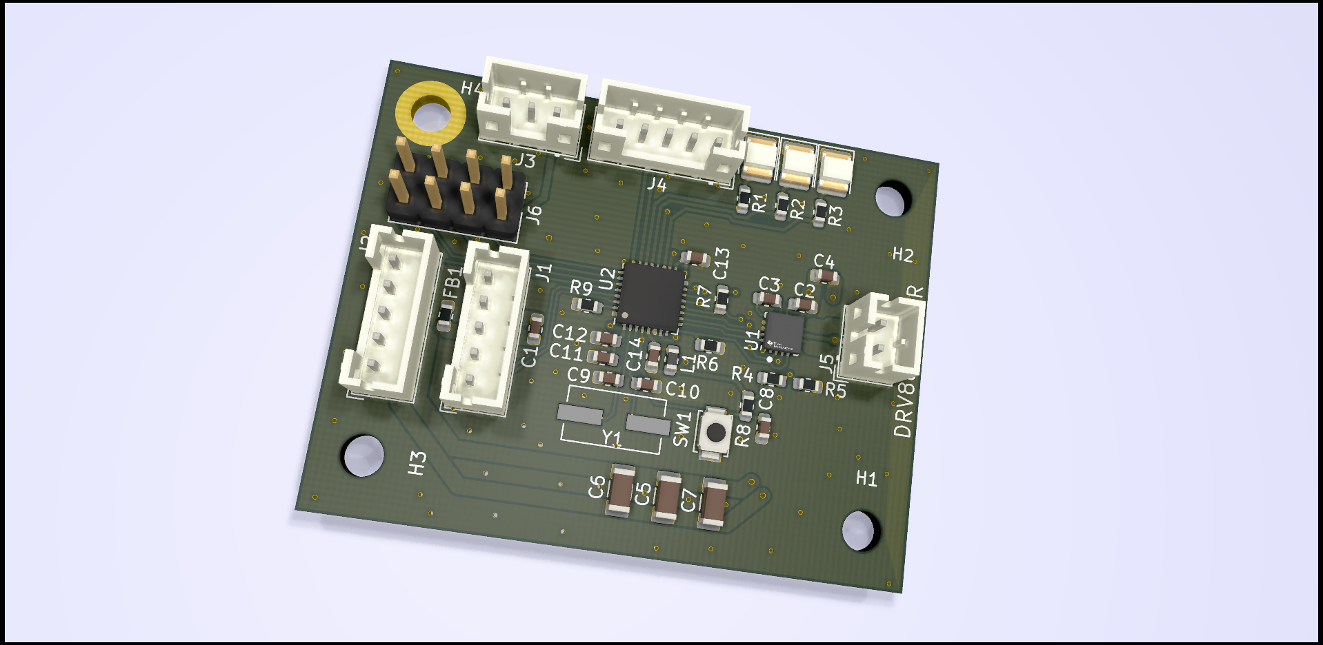
  • 0.0.1 - Initial proposal board for development board schematic and layout.
    • STM32F302K8 MCU - Small package and seemingly enough processing power for everything we need.
    • DRV8876RGTR Driver - Has more than double the current needed and provides an inbuilt current sensing solution (hopefully good enough)

Costs

Here I will keep track of how much you have to pay for each of the more expensive bits so you have an idea of how much a working GISMo will cost you.

FAQ

I have barely started this project and everytime I tell somebody about it, I get the same questions, so here we go:

  • Why not use a normal DC motor with drivers tailored for each project:

    • Cause I like modular! It saves time and you dont have to do everything multiple times. Plus, a lot of the stuf you find online if you are 3D printing, is already made for this size motor. Plus Plus, sorting out motor specifications, gearboxes, making gears (when necessary) is all just a pain, this one can do a lot of the stuff I need for anyway (robotic arms and legged robots).
  • Why not just buy a smart servo? this one will probably cost almost the same as the comercial ones.

    • For one, i Hope to make it at least the same price as the "cheap" smart servos. But really, mainly, so I can have full power over its features and its firmware. Also cause its fun!

For now that is it, lets see what comes next :)

License

Everything under this repository is free to use unless it is used to generate profit. The license states that it CAN be used for comercial puproses, however an agreement have to be reached between the original creator of this project (Werner Thomassen Andrade) and the interested parties before that can happens.

Parts

47
QtyValueFootprintReferences
410nFCapacitor_SMD:C_0603_1608MetricC8, C12, C13, C14
3100RResistor_SMD:R_0603_1608MetricR1, R2, R3
347uFCapacitor_SMD:C_1206_3216MetricC5, C6, C7
3MountingHoleMountingHole:MountingHole_3.2mm_M3H1, H2, H3
20.1uFCapacitor_SMD:C_0603_1608MetricC2, C4
210kResistor_SMD:R_0603_1608MetricR8, R9
210pFCapacitor_SMD:C_0603_1608MetricC9, C10
2I2CConnector_JST:JST_PH_B5B-PH-K_1x05_P2.00mm_VerticalJ1, J2
10.022ufCapacitor_SMD:C_0603_1608MetricC3
11.5KResistor_SMD:R_0603_1608MetricR4
1100ufCapacitor_SMD:C_0603_1608MetricC1
110KResistor_SMD:R_0603_1608MetricR7
116MHzCrystal:Crystal_SMD_ECS_CSM3X-2Pin_7.6x4.1mmY1
122uhInductor_SMD:L_0603_1608MetricL1
12KResistor_SMD:R_0603_1608MetricR6
14.7uFCapacitor_SMD:C_0603_1608MetricC11
150KResistor_SMD:R_0603_1608MetricR5
1600ohmResistor_SMD:R_0603_1608MetricFB1
1BLED_SMD:LED_1210_3225MetricD3
1Conn_01x02Connector_JST:JST_PH_B2B-PH-K_1x02_P2.00mm_VerticalJ5
1Conn_02x04_Odd_EvenConnector_PinHeader_2.54mm:PinHeader_2x04_P2.54mm_VerticalJ6
1DEBUGConnector_JST:JST_PH_B5B-PH-K_1x05_P2.00mm_VerticalJ4
1DRV8876RGTRTI DRV:Texas_Instruments-RGT0016C-0-0-MFGU1
1GLED_SMD:LED_1210_3225MetricD2
1MountingHole_PadMountingHole:MountingHole_3.2mm_M3_DIN965_PadH4
1PA0TestPoint:TestPoint_Pad_1.0x1.0mmTP2
1PA6TestPoint:TestPoint_Pad_1.0x1.0mmTP3
1PA7TestPoint:TestPoint_Pad_1.0x1.0mmTP4
1PA8TestPoint:TestPoint_Pad_1.0x1.0mmTP5
1PB0TestPoint:TestPoint_Pad_1.0x1.0mmTP1
1PositionConnector_JST:JST_PH_B3B-PH-K_1x03_P2.00mm_VerticalJ3
1RLED_SMD:LED_1210_3225MetricD1
1RESETButton_Switch_SMD:SW_SPST_B3U-1000PSW1
1STM32F302K8UxPackage_DFN_QFN:QFN-32-1EP_5x5mm_P0.5mm_EP3.45x3.45mmU2

More from wandrade/GISMo

1
  • 2 layers18 × 29.9 mmSmartServo, the printed circuit board in 3D

    SmartServo

    wandrade/GISMo

    Greatly Inteligent Servo Motor (G.I.S.Mo) - Adapt a MG995 or similar servo to a propper smart servo with current sensing and cool control methods (cause the ones that are cheap are sh**, and the other ones too)

    47 parts6GPL-3.0

Similar boards

  • 2 layers30 × 61.3 mmModuleV450, the printed circuit board in 3D

    ModuleV450

    stuartpittaway/diyBMSv4

    Version 4 of the diyBMS

    47 parts1.1k
  • 2 layers114 × 61.4 mmLHS Breakbeat, the printed circuit board in 3D

    LHS Breakbeat

    lhndo/LH-Stinger

    Fast, Precise, Cartesian, FDM 3D Printer

    47 parts1.1k
  • 2 layers80 × 35 mmV0 Display RP2040, the printed circuit board in 3D

    V0 Display RP2040

    VoronDesign/Voron-Hardware

    Cool Hardware designed by the Voron Design group

    47 parts1.1kGPL-3.0
  • 2 layers100 × 66.7 mmMacroPad1, the printed circuit board in 3D

    MacroPad1

    hackclub/OnBoard

    💡 Join 1,000 teenagers and make your first PCB with a $100 grant!

    47 parts915
  • 2 layers100 × 100 mmReviung34-split L, the printed circuit board in 3D

    Reviung34-split L

    gtips/reviung

    The REVIUNG41 is 41-key column staggered keyboard.

    47 parts517MIT
  • 2 layers36.3 × 99.1 mmJETT STATION SELECT, the printed circuit board in 3D

    JETT STATION SELECT

    jrsteensen/OpenHornet

    OpenHornet 1:1 F/A-18C Simulator Repository

    47 parts431
  • 2 layers50 × 20.5 mmOtterIron PRO Bot, the printed circuit board in 3D

    OtterIron PRO Bot

    Jana-Marie/Otter-Iron-PRO

    USB-PD soldering station for JBC C245 handles.

    47 parts321
  • 2 layers33.8 × 131 mmMicrocontrollerInputModule, the printed circuit board in 3D

    MicrocontrollerInputModule

    FrameworkComputer/InputModules

    Reference designs and documentation for the Input Module system in the Framework Laptop 16

    47 parts245

Questions

How big is the SmartServo PCB?

It measures 47.6 × 36.8 mm and has 2 copper layers, 1.6 mm thick.

What parts does the SmartServo use?

47 parts. The full list of its parts is on this page, with links to each part's symbol and footprint where PCBKit's library has them.

Where can I download the SmartServo KiCad files?

From the wandrade/GISMo repository on GitHub, at the commit this page was made from: the board is Hardware/DevBoard/SmartServo.kicad_pcb. PCBKit opens the board in the browser, with nothing to install.

Can I use the SmartServo design in my own project?

Its repository publishes it under the GPL-3.0 licence: you may reuse it on that licence's terms (keep the author's notice, and for a copyleft licence share your changes alike).