
2 layers98 × 27 mm

 vsreality/swd-adapter
Compact passive SWD adapter connecting ARM20 debuggers to TC2030 and 10-pin Cortex SWD cables. Features a 26 × 32 mm PCB, rounded corners, grounded M3 mounting holes, and pin labels. Includes KiCad 10 source files, 3D previews, Gerbers, drill files, and assembly instructions.
Swd adapter is an open-source printed circuit board by vsreality, from the vsreality/swd-adapter repository on GitHub. It is a 2-layer board of 26 × 32 mm with 5 parts on 14 nets, routed with 73 tracks and 1 via.
It belongs with the interfaces and adapters boards of this library.
A passive adapter connecting an ARM20 debugger to a Tag-Connect TC2030 cable or a 10-pin Cortex SWD cable.
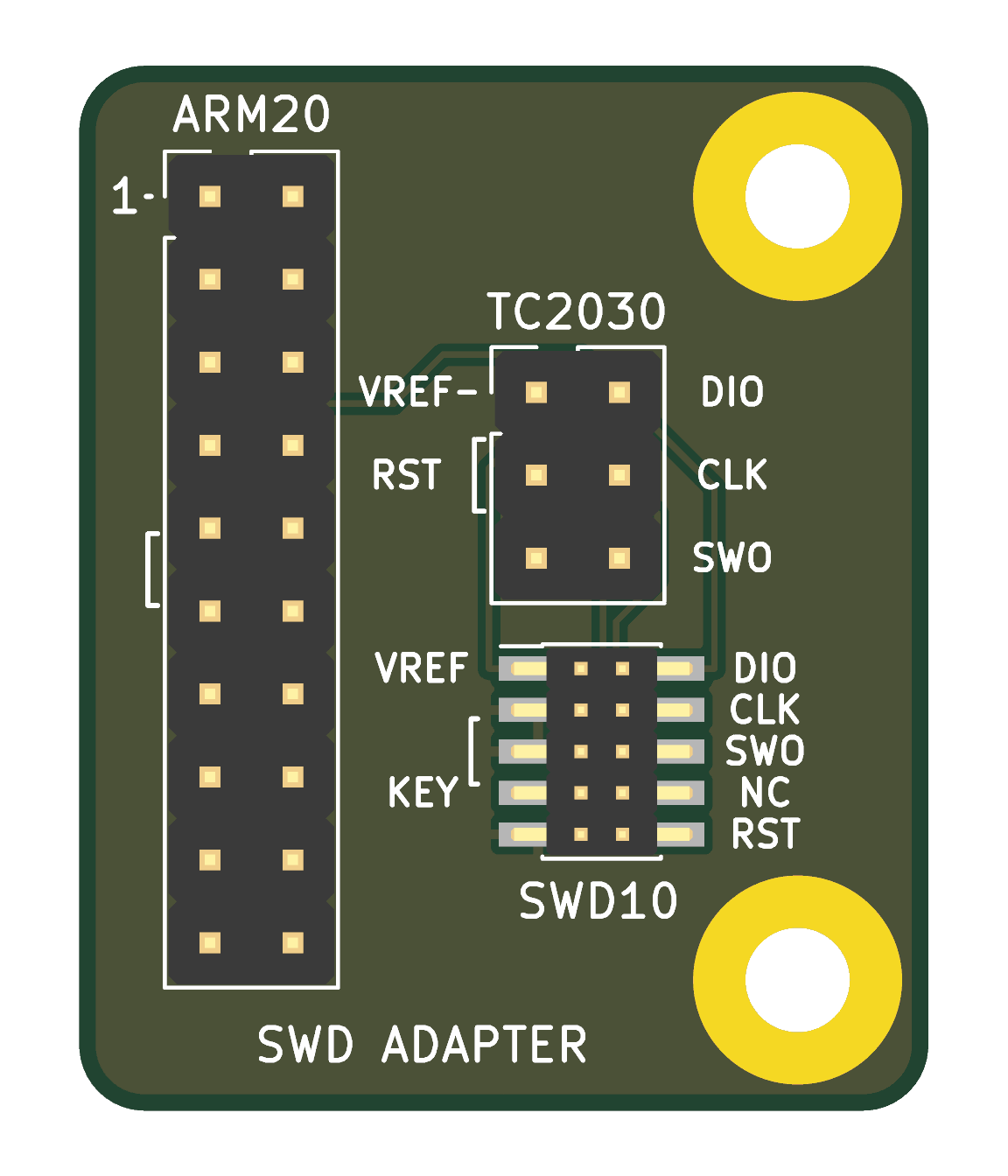
Open swd-adapter.kicad_pro in KiCad 10 or newer. The schematic and fully routed PCB are included. A rendered schematic preview is available without opening KiCad.
| Reference | Board label | Header |
|---|---|---|
| J1 | ARM20 | 2×10, 2.54 mm, unshrouded through-hole |
| J2 | TC2030 | 2×3, 2.54 mm, unshrouded through-hole |
| J3 | SWD10 | 2×5, 1.27 mm, surface-mount |
| Signal | ARM20 | TC2030 | SWD10 |
|---|---|---|---|
| VTREF | 1 | 1 | 1 |
| SWDIO / DIO | 7 | 2 | 2 |
| SWCLK / CLK | 9 | 4 | 4 |
| SWO | 13 | 6 | 6 |
| nRESET / RST | 15 | 3 | 10 |
| GND | Even pins 4–20 | 5 | 3, 5, 9 |
The back silkscreen labels every ARM20 signal pin:
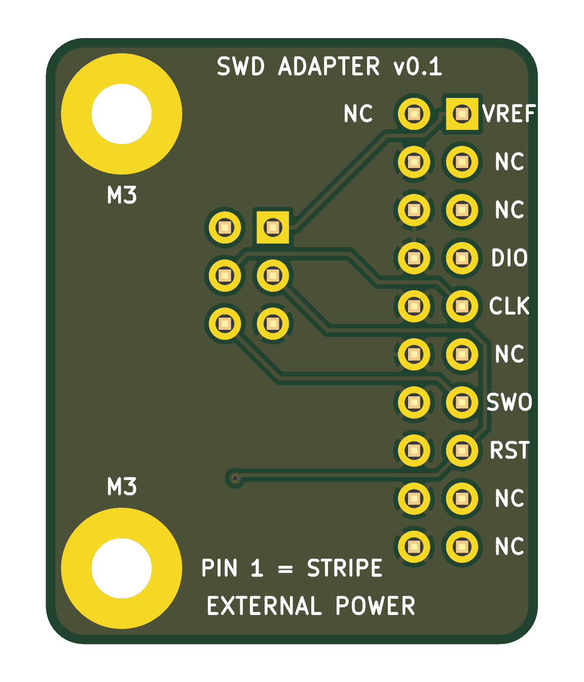
ARM20 pins 2, 3, 5, 11, 17 and 19 are unused. SWD10 pin 7 is the key position; pin 8 is unused. This is an SWD adapter, not a full JTAG adapter. GND words are omitted from silkscreen; electrical ground connections remain present.
TC2030 accepts the ordinary IDC end of a TC2030-IDC or TC2030-IDC-NL cable, not its pogo-pin end.
Mounting-hole centers are 22 mm from the left edge and 4 mm from the top and bottom edges. Each has a 7 mm track/via keepout for hardware. Plated barrels connect the exposed ground pads on both faces, so extra mounting-hole vias are unnecessary.
Exports include both copper layers, masks, silkscreens, board outline and matching metric Excellon drills. The NPTH file is intentionally empty because the mounting holes are plated. Assembly is manual.
The production export was checked with KiCad 10:
See release check reports for details and ignored check categories. Manufacturing uses the footprints saved in the board. Physical cable housing fit and operation have not yet been tested on a prototype.
| Path | Contents |
|---|---|
swd-adapter.kicad_* | Current KiCad project, schematic and PCB |
manufacturing/ | Fabrication exports |
production/ | Dated release and ordering archives |
preview/ | Front and back board renders, and a schematic preview |
routing/ | Historical router exchange files and synchronization script |
*.py | Historical construction/editing scripts |
The saved KiCad files are authoritative. Do not replay the historical scripts or router session over the finished board. generate.py refuses to overwrite an existing PCB.
.gitignore excludes KiCad local state, locks, backups, logs and downloaded routing tools. Production archives and previews are intentionally tracked. .gitattributes preserves exact file bytes, including fabrication exports.
| Qty | Value | Footprint | References |
|---|---|---|---|
| 2 | MountingHole_Pad | MountingHole:MountingHole_3.2mm_M3_Pad | H1, H2 |
| 1 | ARM20 / ST-LINK | Connector_PinHeader_2.54mm:PinHeader_2x10_P2.54mm_Vertical | J1 |
| 1 | Cortex SWD SMD | Connector_PinHeader_1.27mm:PinHeader_2x05_P1.27mm_Vertical_SMD | J3 |
| 1 | TC2030 cable | Connector_PinHeader_2.54mm:PinHeader_2x03_P2.54mm_Vertical | J2 |
It measures 26 × 32 mm and has 2 copper layers, 1.6 mm thick.
5 parts. The full list of its parts is on this page, with links to each part's symbol and footprint where PCBKit's library has them.
From the vsreality/swd-adapter repository on GitHub, at the commit this page was made from: the board is production/v0.1-2026-09-08/source/swd-adapter.kicad_pcb and its schematic production/v0.1-2026-09-08/source/swd-adapter.kicad_sch. PCBKit opens the board in the browser, with nothing to install.
Its repository states no licence, so its author keeps all rights: ask vsreality before reusing the design.

joypad-ai/joypad-os
Universal controller firmware for building adapters, dongles, and custom controllers.

OLIMEX/OLINUXINO
OLINUXINO is Open Source / Open Hardware, low cost from EUR 24 Linux Industrial grade Single Board Computer capable to operate -25+85C

jamro/tiny-engineer
A small desktop robot that brings an AI coding assistant to life, physically acting out when it reads files, thinks, writes code, and finishes work.

hackclub/OnBoard
💡 Join 1,000 teenagers and make your first PCB with a $100 grant!


Luos-io/luos_engine
Open-source and real-time orchestrator for cyber-physical-systems, to easily design, test and deploy embedded applications and digital twins.