4 layers65 × 75 mm
169 gateway
vsb-fei-440/LoRa-169
A complete LoRa system for the 169 MHz band (169.4375 MHz): battery-powered nodes, a gateway board, a Raspberry Pi bridge to MQTT and Grafana dashboards.
82 parts

 vsb-fei-440/LoRa-169
A complete LoRa system for the 169 MHz band (169.4375 MHz): battery-powered nodes, a gateway board, a Raspberry Pi bridge to MQTT and Grafana dashboards.
169 node is an open-source printed circuit board by vsb-fei-440, from the vsb-fei-440/LoRa-169 repository on GitHub. It is a 4-layer board of 50 × 55.9 mm with 71 parts on 63 nets, routed with 527 tracks and 254 vias.
It is built around the ATMEGA328P-MU, CH340N and DS18B20, with the USBLC6-2SC6 among its other parts. Its parts include 23 capacitors, 22 resistors, 10 ICs, 5 connectors and 3 diodes. It belongs with the AVR (ATmega, ATtiny) boards of this library.


A complete LoRa system for the 169 MHz band (169.4375 MHz): battery-powered nodes, a gateway board, a Raspberry Pi bridge to MQTT and Grafana dashboards. It was built at VSB - Technical University of Ostrava for teaching and for coverage measurements of the 169 MHz band.
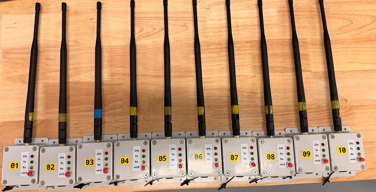
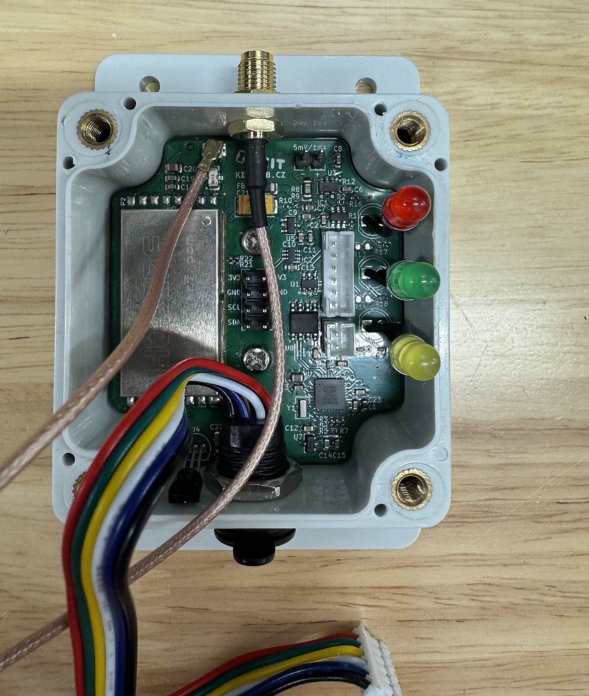
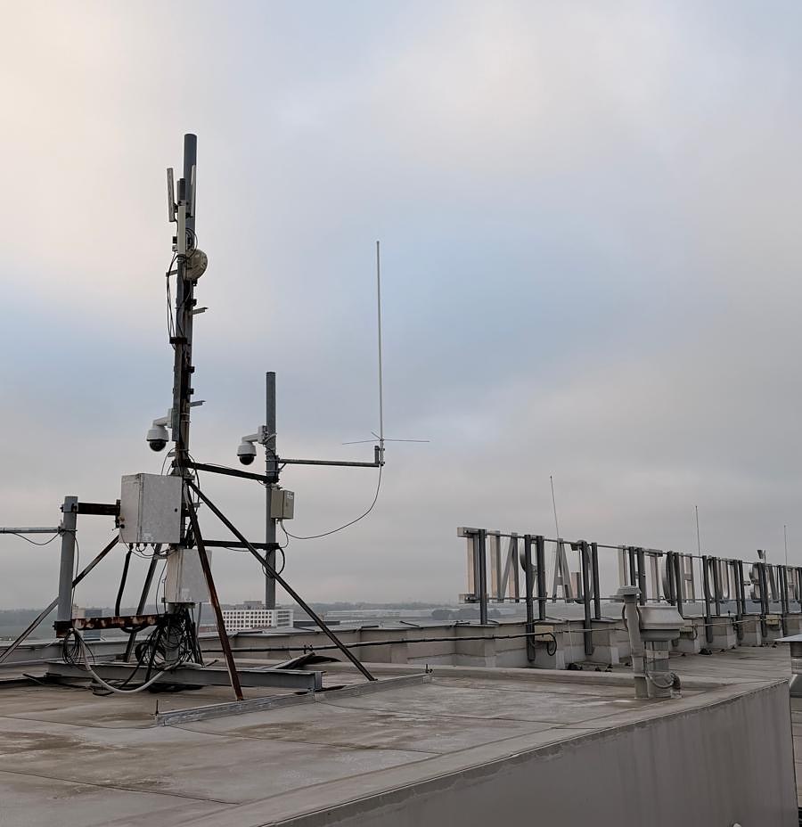
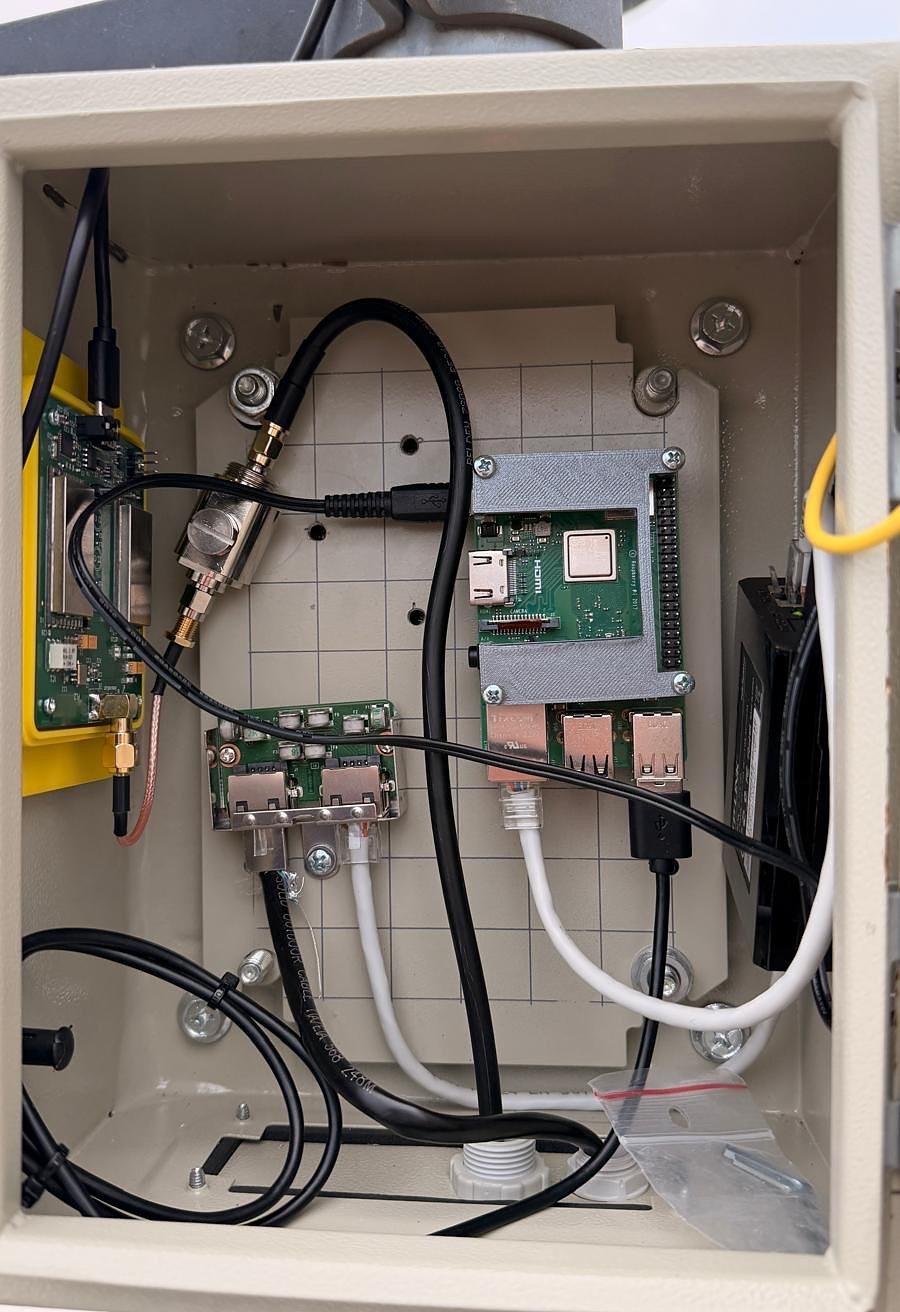
| Node | Gateway on the roof | Gateway and Raspberry Pi in the mast cabinet |
|---|---|---|
 |  |  |
flowchart LR
    N1[Node 01] -- "LoRa 169 MHz" --> GW
    N2[Node ...] -- "LoRa 169 MHz" --> GW
    GW -- "ACK" --> N1
    GW[Gateway board<br/>2x RFM98PW] -- "USB serial" --> RPI[Raspberry Pi<br/>lora169-gw]
    RPI -- "MQTT" --> BROKER[(MQTT broker)]
    BROKER --> TIG[Telegraf + InfluxDB]
TIG --> GRAF[Grafana dashboards]Radio settings are fixed for the whole system: 169.4375 MHz, bandwidth 41.7 kHz, SF12, coding rate 4/5, explicit header, CRC, low data rate optimisation.
| Folder | Content |
|---|---|
hardware/node | KiCad project of the node, schematic PDF, JLCPCB production files |
hardware/gateway | KiCad project of the gateway board, schematic PDF, JLCPCB production files |
firmware/node-library | Arduino library LoRa169Node for the node, with ten examples |
firmware/gateway | Firmware of the gateway board (USB radio modem) |
firmware/tools | Bring-up and diagnostic sketches, bootloader script, PC test console |
gateway-rpi | lora169-gw, the Raspberry Pi bridge between the gateway and MQTT (C) |
grafana | Dashboards and scripts to generate and update them |
docs | Documentation |
| Topic | Document |
|---|---|
| System overview and design decisions | docs/architecture.md |
| Node hardware | docs/hardware-node.md |
| Gateway hardware | docs/hardware-gateway.md |
| Getting started: bootloader, first node, first gateway | docs/getting-started.md |
| Node library and examples | docs/node-firmware.md |
| Gateway firmware and its USB protocol | docs/gateway-firmware.md |
| Raspberry Pi bridge: install, configuration, remote update | docs/gateway-rpi.md |
| Radio frames, ACK and MQTT messages | docs/protocol.md |
| Grafana dashboards | docs/grafana.md |
| RF path measurements (VNA) | docs/rf-measurements.md |
| Known issues and notes for the next revision | docs/known-issues.md |
hardware/*/production and solder the parts that are
not in the JLCPCB BOM (node,
gateway).10_Measure with your node ID.LoRa-169_GW, connect it to a Raspberry Pi over USB and install
lora169-gw (guide).Software (firmware, Raspberry Pi bridge, scripts): MIT, see LICENSE. Hardware (KiCad projects and production files): CERN-OHL-P v2, see hardware/LICENSE.
| Qty | Value | Footprint | References |
|---|---|---|---|
| 14 | 100n | Capacitor_SMD:C_0603_1608Metric | C1, C2, C3, C5, C6, C7, C8, C11, C15, C16, C17, C18, C22, C23 |
| 6 | 100k | Resistor_SMD:R_0402_1005Metric | R1, R7, R9, R10, R11, R16 |
| 6 | 1u | Capacitor_SMD:C_0603_1608Metric | C9, C10, C12, C13, C14, C19 |
| 4 | 22 | Resistor_SMD:R_0402_1005Metric | R3, R4, R5, R20 |
| 3 | 100 | Capacitor_SMD:C_0402_1005Metric | R17, R18, R19 |
| 3 | 4k7 | Resistor_SMD:R_0402_1005Metric | R15, R21, R22 |
| 2 | 10u | Capacitor_SMD:C_0805_2012Metric | C4, C20 |
| 2 | 5.1k | Resistor_SMD:R_0603_1608Metric | R13, R14 |
| 2 | MCP1700x-330xxTT | Package_TO_SOT_SMD:SOT-23 | U5, U7 |
| 2 | MountingHole | MountingHole:MountingHole_3.2mm_M3 | H1, H2 |
| 1 | 0R1 | Resistor_SMD:R_1206_3216Metric | R8 |
| 1 | 100u | Capacitor_Tantalum_SMD:CP_EIA-6032-28_Kemet-C | C21 |
| 1 | 10k | Resistor_SMD:R_0402_1005Metric | R6 |
| 1 | 10u | Inductor_SMD:L_0603_1608Metric | L1 |
| 1 | 1k | Capacitor_SMD:C_0402_1005Metric | R12 |
| 1 | 20k | Resistor_SMD:R_0402_1005Metric | R2 |
| 1 | ATmega328P-M | Package_DFN_QFN:QFN-32-1EP_5x5mm_P0.5mm_EP3.1x3.1mm | U2 |
| 1 | CH340N | Package_SO:JEITA_SOIC-8_3.9x4.9mm_P1.27mm | U8 |
| 1 | Conn_02x04_Counter_Clockwise | Connector_PinHeader_2.54mm:PinHeader_2x04_P2.54mm_Vertical | J4 |
| 1 | Conn_Coaxial | Connector_Coaxial:U.FL_Hirose_U.FL-R-SMT-1_Vertical | J5 |
| 1 | DS18B20 | Package_TO_SOT_THT:TO-92_Inline | U4 |
| 1 | FerriteBead | Inductor_SMD:L_1206_3216Metric | FB1 |
| 1 | INA180A2 | Package_TO_SOT_SMD:SOT-23-5 | U3 |
| 1 | I_RAW | Connector_PinHeader_2.54mm:PinHeader_1x02_P2.54mm_Vertical | J3 |
| 1 | LFCN-190 | Filter:Filter_Mini-Circuits_FV1206 | FL1 |
| 1 | LOGO | hoperf_rf98:logo_xs | G*** |
| 1 | POWER_RED | LED_THT:LED_D5.0mm | D1 |
| 1 | RFM98PW-169S2 | kicad-footprint-collection:XCVR_RFM98PW-169S2_EDIT | U6 |
| 1 | RX_GREEN | LED_THT:LED_D5.0mm | D3 |
| 1 | Resonator | Crystal:Resonator_SMD_Murata_CSTxExxV-3Pin_3.0x1.1mm | Y1 |
| 1 | TPS22919DCKR | kicad-footprint-collection:SOT65P210X110-6N | IC2 |
| 1 | TPS2553DDBVR_EDIT | kicad-footprint-collection:SOT95P280X145-6N | IC1 |
| 1 | TX_BTN | Connector_JST:JST_PH_B2B-PH-K_1x02_P2.00mm_Vertical | J2 |
| 1 | TX_GREEN | LED_THT:LED_D5.0mm | D2 |
| 1 | TestPoint | TestPoint:TestPoint_Pad_D1.0mm | TP1 |
| 1 | USB-C | Connector_JST:JST_PH_B6B-PH-K_1x06_P2.00mm_Vertical | J1 |
| 1 | USBLC6-2SC6 | Package_TO_SOT_SMD:SOT-23-6 | U1 |
vsb-fei-440/LoRa-169
A complete LoRa system for the 169 MHz band (169.4375 MHz): battery-powered nodes, a gateway board, a Raspberry Pi bridge to MQTT and Grafana dashboards.

adbik4/DL-FinalProject
The design and implementation of a measurement and data logging system based on ATmega328pb microcontroller. The system is intended for measuring temperature and pressure using dedicated digital sensors: DS18B20 and…

dilshan/24ch-usb-high-voltage-driver
24-Channel USB high voltage driver.

eurovibes/rack-ser-adapter
rack-ser-adapter is provided under the terms of the CERN-OHL-S license version 2 as provided in the LICENSES/CERN-OHL-S-2.0 file.


eurovibes/sertest-ng
Serial interfaces like RS-232, RS-422/485 or CAN bus are even used in this modern times. While reworking the 8250 driver in the Linux kernel jogness faced plethora of nasty hardware dedication with modern serial…

It measures 50 × 55.9 mm and has 4 copper layers, 1.61 mm thick.
71 parts, built around the ATMEGA328P-MU, CH340N, DS18B20 and USBLC6-2SC6. The full list of its parts is on this page, with links to each part's symbol and footprint where PCBKit's library has them.
From the vsb-fei-440/LoRa-169 repository on GitHub, at the commit this page was made from: the board is hardware/node/169_node.kicad_pcb and its schematic hardware/gateway/169_gateway.kicad_sch. PCBKit opens the board in the browser, with nothing to install.
Its repository states no licence, so its author keeps all rights: ask vsb-fei-440 before reusing the design.