4 layers65 × 56 mm
Picalor pcb
ul-gh/Picalor
Picalor - Multi-Channel Heat Balance Calorimetry on the Raspberry Pi
117 parts3GPL-3.0
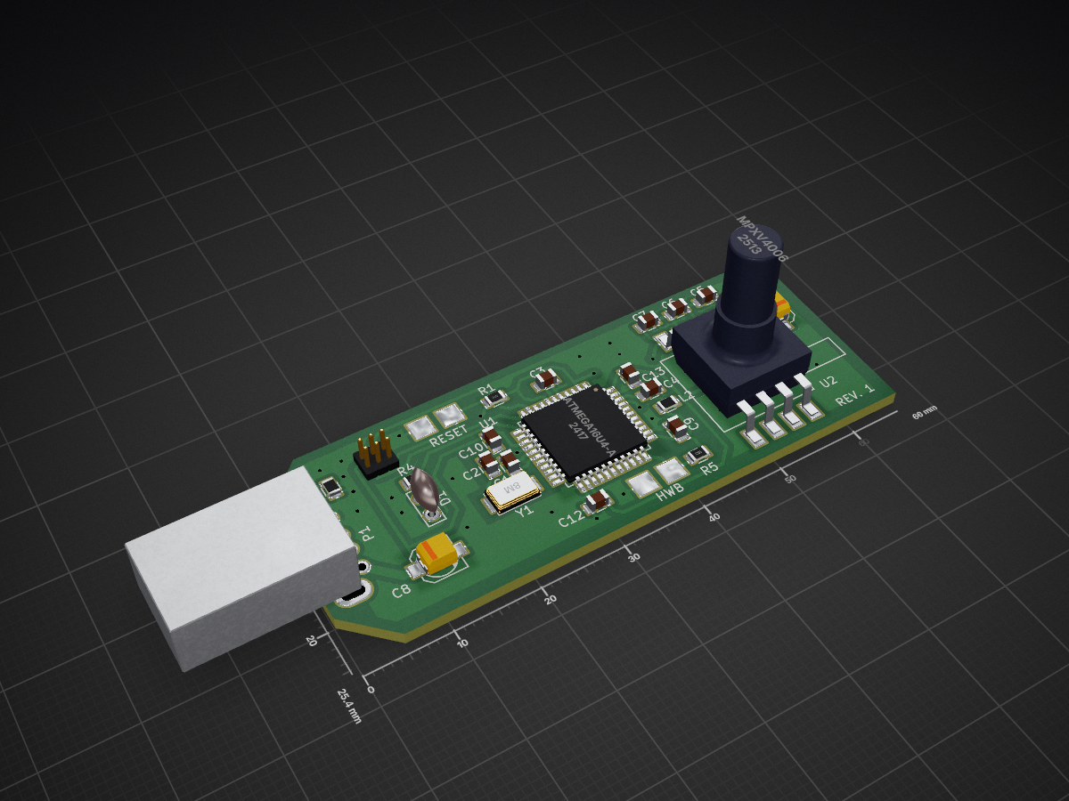
 vpatkov/breath-controller10
USB-MIDI Breath Controller
Breath controller is an open-source printed circuit board by vpatkov, from the vpatkov/breath-controller repository on GitHub. It is a 2-layer board of 66 × 25.4 mm with 57 parts on 40 nets, routed with 247 tracks and 13 vias.
It is built around the ATMEGA16U4-AU, MPXV4006DP and BLM21AG102SN1. Its parts include 13 capacitors, 5 resistors, 2 ICs, 2 connectors and 2 inductors. It belongs with the audio and music boards and the AVR (ATmega, ATtiny) boards of this library.


A device that converts breath pressure to MIDI data.
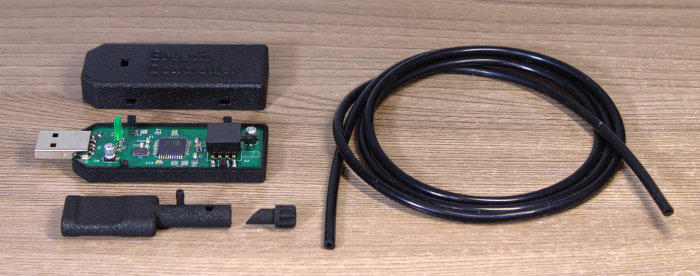
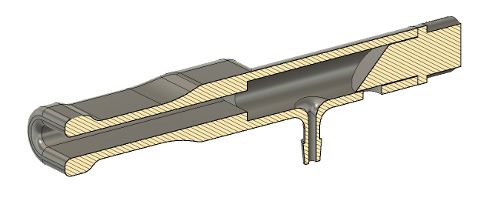
The mouthpiece has an adjustable valve for drain control.
The LED's brightness is proportional to the output MIDI value. Until the USB interface is successfully configured the LED is fully on.
During initialization, the auto-zeroing of the pressure sensor is performed. So, don't blow into the mouthpiece when plugging the device.
The mouthpiece and the case are 3D printed from STL files
in the 3d directory. The silicone tube is 4 mm OD and 2 mm ID.
By default, the device sends the pressure data as CC2
messages on channel 1, with maximal input and output ranges,
and linear response. These settings can be changed using the
configuration tool (in the software directory).
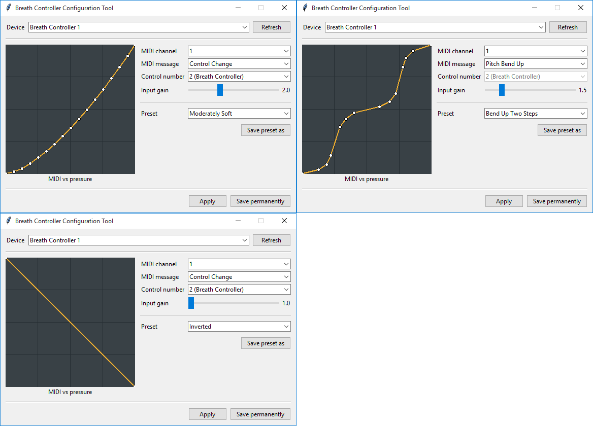
The response curve can be edited by mouse: the left button adds and drags points, the right button removes them, and the middle button resets the curve to default. The curve can be arbitrary.
The input gain is applied before the curve.
Settings can be applied to the device temporary (until power is removed) or saved permanently (in EEPROM).
The software works on Windows and Linux (both tested), and should work on macOS.
The device is implemented with ATmega16U4 MCU and MPXV4006GP pressure sensor. The MCU has hardware USB controller, ADC, EEPROM, and other peripherals, eliminating the need of additional chips. In firmware, LUFA USB stack is used.
The pressure is sampled by ADC, averaged for 8 ms, applied auto-zero, input gain, the response curve, and then is sent to the host if the value differs from the previously sent one.
The response curve is implemented by a 128-byte lookup table. It's simple and allows arbitrary curves.
The runtime configuration is implemented with SysEx messages (see below) from the host. The configuration tool is written in Python using MIDO and Tkinter libraries.
Set the MIDI channel: F0 7D 00 XX F7 where XX is a MIDI
channel (1..16).
Set the MIDI message: F0 7D 01 XX F7 where XX is 00 for Control Change,
01 for Channel Pressure, 02 for Pitch Bend Up, 03 for Pitch Bend Down.
Set the control number: F0 7D 02 XX F7 where XX is a control number (0..127).
Set the input gain: F0 7D 03 XX F7 where XX is input gain multiplied
by 10. XX must be in range 10..40.
Set the response curve: F0 7D 04 X0 X1 ... X127 F7 where
X0 X1 ... X127 is a 128-byte lookup table. Each Xn must be in the range 0..127.
Save current settings to EEPROM: F0 7D 05 F7.
Presets used by the configuration tool are just plain text files containing following lines:
midi_channel followed by a decimal number (1..16);midi_message followed by a control_change, channel_pressure, pitch_bend_up,
or pitch_bend_down;control_number followed by a decimal number (0..127);input_gain followed by a floating point decimal number
(between 1.0 and 4.0);curve followed by a space delimited list of points (x,y)
where x and y are decimal numbers (0..127), assuming
linear interpolation between the points.You can ignore some of the settings, they will not changed after loading the preset. For example, you can create curve-only presets.
Preset must have .preset file extension and lie in the
software/presets directory.
ATmega16U4-AU is shipped with a pre-installed USB bootloader and can be programmed with the official FLIP software or dfu-programmer. To enter the bootloader short HWB pin to GND during reset (there are screwdriver-compatible pads for that on the PCB). Just in case, the PCB has pogo-compatible pads for ISP programming. The fuses are factory default.
Unless otherwise noted, this work is licensed under Creative Commons Zero 1.0.

| Qty | Value | Footprint | References |
|---|---|---|---|
| 5 | 100n | Capacitors_SMD:C_0805 | C4, C9, C10, C12, C13 |
| 2 | 10k | Resistors_SMD:R_0805 | R1, R5 |
| 2 | 10u/16V | Capacitors_SMD:c_elec_4x5.3 | C8, C11 |
| 2 | 1u | Capacitors_SMD:C_0805 | C3, C5 |
| 2 | 22 | Resistors_SMD:R_0805 | R2, R3 |
| 2 | 22p | Capacitors_SMD:C_0805 | C1, C2 |
| 2 | BLM21AG102 | Resistors_SMD:R_0805 | L1, L2 |
| 2 | Jumper_NO_Small | breath-controller:JUMPER_PADS | JP1, JP2 |
| 1 | 10n | Capacitors_SMD:C_0805 | C6 |
| 1 | 1k | Resistors_SMD:R_0805 | R4 |
| 1 | 470p | Capacitors_SMD:C_0805 | C7 |
| 1 | 8M | breath-controller:CRYSTAL_5032_2PIN | Y1 |
| 1 | ATMEGA16U4-A | Housings_QFP:TQFP-44_10x10mm_Pitch0.8mm | U1 |
| 1 | CONN_02X03 | breath-controller:POGO_AVR_ISP6 | P2 |
| 1 | LED | breath-controller:LED_2X5 | D1 |
| 1 | MPXV4006 | breath-controller:MPXV4006GP | U2 |
| 1 | USB_A | breath-controller:USB_A_4UCON_10016 | P1 |
The 28 most common of 57 parts.
It measures 66 × 25.4 mm and has 2 copper layers, 1.6 mm thick.
57 parts, built around the ATMEGA16U4-AU, MPXV4006DP and BLM21AG102SN1. The full list of its parts is on this page, with links to each part's symbol and footprint where PCBKit's library has them.
From the vpatkov/breath-controller repository on GitHub, at the commit this page was made from: the board is hardware/breath-controller.kicad_pcb. PCBKit opens the board in the browser, with nothing to install.
Its repository states no licence, so its author keeps all rights: ask vpatkov before reusing the design.
ul-gh/Picalor
Picalor - Multi-Channel Heat Balance Calorimetry on the Raspberry Pi

UzixLS/rgb2svideo
Converts RGB + Sync analog signal to S-Video (and also Composite).


