2 layers52.2 × 52.2 mm
Base
google/mozc-devices
Circuit diagrams and firmware source code for Gboard DIY keyboards
43 parts3kApache-2.0

 vpalaga/DrawMachine1
x, y robot steered by FCODE Instructions
DrawMv2.0 is an open-source printed circuit board by vpalaga, from the vpalaga/DrawMachine repository on GitHub. It is a 2-layer board of 97.5 × 67.3 mm with 43 parts on 59 nets, routed with 393 tracks and 8 vias.
Its parts include 11 connectors, 10 capacitors, 6 resistors, 3 ICs and 2 diodes. It belongs with the robots and motor control boards and the RP2040 boards of this library.
An XY pen plotter driven by a Raspberry Pi Pico and a home-made G-code dialect called FCODE.
Feed it a .dxf drawing, it works out where the pen has to go, and a Pico steps three stepper motors (X, Y and a Z pen lift) to draw it on A4 paper.
The goal: a 100% working, reliable XY plotter that does my homework. Partially based on the Scrabble bot.
flowchart LR
    A[".dxf drawing"] --> B["FCODEgenerator<br/>Python"]
    B --> C[".FCODE file<br/>absolute positions in mm"]
    C --> D["DataSendToPico<br/>Python, over USB serial"]
    D --> E["Pico firmware<br/>C++, relative steps"]
    E --> F["TMC2209 drivers<br/>X, Y, Z steppers"]
FCODEgenerator reads a DXF (or you script the pen by hand), centres it on the paper, reorders the strokes to minimise pen travel, and writes an .FCODE text file. Positions are in millimetres.DataSendToPico reads the FCODE file line by line, converts millimetres to motor steps, range-checks every move and sends one command at a time to the Pico over USB CDC (virtual serial port). It waits for the Pico to confirm each command.StepperDriver-pico is the firmware. It parses each command, coordinates X and Y step pulses so both axes finish a move together, lifts and lowers the pen, and homes against the end switches.| Path | What's in it |
|---|---|
FCODEgenerator/ | DXF reader, path optimiser, FCODE writer and preview renderer (Python) |
FCODEgenerator/dxfexamples/ | Sample DXF files to try |
DataSendToPico/ | Host-side sender: file runner, mm to steps conversion, serial transport, test CLI and GUI (Python) |
StepperDriver-pico/ | Pico firmware (C++ / Pico SDK) |
StepperDriver-pico/Pico_pins_map.txt | ASCII Pico pinout showing which GPIO does what |
StepperDriver-pico/bresenham_test.py | Draws the step pattern of the line algorithm with PIL, used to design the move function |
pcb/2.0/DrawMv2.0/ | Current board: KiCad project for the v2.0 controller PCB |
pcb/test/ | Retired first prototype board (v1), kept for reference only |
pcb2_0_schematic.pdf | PDF of the v2.0 schematic |
images/ | Documentation images |
SZS.motorDriver.cpp)A full ASCII drawing of the Pico with every pin is in StepperDriver-pico/Pico_pins_map.txt.
| Function | GPIO |
|---|---|
| X stepper: STEP / DIR / EN | 13 / 12 / 10 |
| Y stepper: STEP / DIR / EN | 8 / 6 / 9 |
| Z stepper: STEP / DIR / EN | 4 / 3 / 5 |
| End switch X / Y / Z | 11 / 7 / 2 |
| Extra buttons B1 / B2 | 18 / 17 |
| LED instruction / console mode | 15 / 14 |
The limit switches connect their GPIO inputs to GND when pressed. The firmware also enables the Pico's internal pull-ups; the external 4.7 kΩ pull-ups were added to stabilize the switch signals. Motor enable pins are active low.
Requirements: Pico SDK 2.2.0, CMake 3.13+, the ARM GNU toolchain (the CMake file is set up for the VS Code Pico extension).
cd StepperDriver-pico
mkdir build && cd build
cmake ..
make -j
Hold BOOTSEL, plug the Pico in, and copy motorDriver.uf2 onto the drive that appears. On boot the console LED blinks six times.
CMakeLists.txt defaults to PICO_BOARD pico. If you are using a Pico 2 / Pico 2 W, configure with cmake -DPICO_BOARD=pico2_w .. (or pico2).
Python 3.10+ is required (the code uses match and X | Y type hints). Run this command from the repository root:
pip install -r requirements.txtThe GUI also needs tkinter, which ships with most Python installers.
Run from inside FCODEgenerator/ (the modules import each other without a package prefix):
cd FCODEgeneratorfrom main import FGenerator
gen = FGenerator("dxfexamples/simpleShape.dxf",
acc=0.1, # curve flattening accuracy in mm
text=False, # True = also draw TEXT / MTEXT as outlines
optimize=True, # reorder strokes to cut pen travel
join_tol=0.5) # points closer than this (mm) count as the same point
gen.generate_instructions()
gen.save(show_visualization=True) # writes .fcodes/simpleShape.FCODE and opens a previewThe preview draws pen-down moves in black, pen-up travel in red and the paper outline in blue, so you can check placement before anything moves.
Plug the Pico in before starting Python, then:
cd DataSendToPico
python -c "from src.Controller import Controller; Controller('../FCODEgenerator/.fcodes/simpleShape.FCODE').do_file()"
This runs the .FCODE file generated above. The controller initializes the pen head, homes X and Y with CLB, then moves the carriage to the configured paper-origin offset. Make sure the carriage has room to move before you run it.
An FCODE file is plain text: a header, then one instruction per line.
header_length 3
name simpleShape
plane_size_mm (297, 210)
MOV 10.0 10.0
PDN
MOV 10.0 200.0
MOV 287.0 200.0
MOV 287.0 10.0
MOV 10.0 10.0
PUP
MOV 76.54 127.03
PDN
MOV 88.93 142.52
...
header_length is the number of header lines (including itself). The sender skips that many lines.MOV x y in a file is an absolute position in mm, measured from the bottom-left corner of the paper. Coordinates are rounded to 0.01 mm.MOV followed by PDN.| Instruction | Args | Meaning | Where it runs |
|---|---|---|---|
MOV x y | 2 | Move the head to (x, y) in mm. Draws if the pen is down | Host converts to relative steps, Pico executes |
PUP | 0 | Pen up | Pico |
PDN | 0 | Pen down | Pico |
WAT s | 1 | Wait s seconds | Pico |
CLB | 0 | Calibrate X and Y against their end switches. The host then moves to the paper-origin offset and zeroes its position | Host and Pico |
HCB | 0 | Calibrate Z (pen head) only | Pico |
SZS steps | 1 | Set the pen up/down stroke length in steps (1-50000) | Pico |
HOM | 0 | HCB, then move to the home position (0, 300) mm | Host only |
SCM m | 1 | Set console mode (0, 1 or 2) | Pico (used internally by the sender) |
PDN returns an error if the firmware already considers the pen down. PUP runs the lift and endstop-seek sequence. The generator avoids emitting redundant pen-state instructions.
To fight lost steps on long jobs, the generator inserts HCB every 200 instructions and CLB every 1000 (head_calibration_after_instruction and overall_calibration_after_instruction).
FGenerator also works without a DXF. Run this from FCODEgenerator/, pass a name instead of a .dxf path, and drive the pen yourself:
from main import FGenerator
from gen import PAPER_SIZES

w, h = PAPER_SIZES["A4"]
gen = FGenerator("outline_A4", text=False, optimize=True, join_tol=0.5)

gen.draw_to(0, h)
gen.draw_to(w, h)
gen.draw_to(w, 0)
gen.draw_to(0, 0)
gen.home()
gen.save()
Available calls: pen_up, pen_down, move_to, travel_to (pen up, then move), draw_to (pen down, then move), draw_polyline, wait, head_calibrate, calibrate, home, save. See example_manual_instructions.py for a 5000-segment random-walk example.
LINE, CIRCLE, ARC, ELLIPSE, LWPOLYLINE, POLYLINE, SPLINE, SOLID / TRACE / 3DFACE, POINT (drawn as a small circle), TEXT / MTEXT / ATTRIB (as outlines, only with text=True). Block references (INSERT) and DIMENSION entities are exploded. Anything else is skipped.
The Pico enumerates as a USB CDC serial device. The sender finds it by USB vendor ID 2E8A.
\n, at most 127 characters.MOV takes relative steps, not millimetres (MOV 800 -1600 moves +1 mm in X and -2 mm in Y).0 = line understood, 1 = rejected (unknown instruction, wrong argument count, or a bad number). After a 1 there is no second reply.0 = OK, 1 = failed (for example a limit switch was never reached during calibration).SMS. The firmware defaults to 50 us half-cycles for X/Y and 100 us for Z; the host adjusts motor speed for each move.CLB drives X and Y towards their switches; HCB moves Z away from its switch, then raises it back until the switch triggers. Every calibration loop has a step limit (400000 for XY, 50000 for Z) so a missing or miswired switch can't make it run forever.SZS steps sets the Z-axis down stroke and the reference length used for the fixed pen-up move and endstop seek.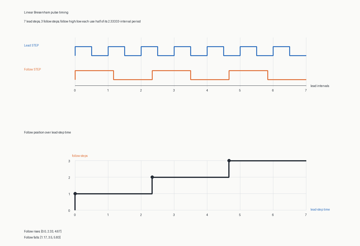
DataSendToPico/)| File | Purpose |
|---|---|
Controller.py | Reads an FCODE file and runs it instruction by instruction, printing progress |
MotorController.py | mm to steps conversion, host travel range checks (380 x 315 mm), paper-origin offset (A4 preset: 33 mm, 48 mm from the switches, so measure your own), request logging |
MotorOverclass.py | Per-axis constants and position bookkeeping (steps per mm, max travel) |
CDC_send.py | Transmitter: finds the Pico, sends commands and reads the two status replies, with a 200 s response timeout |
CDC_test.py | Tiny CLI: type raw instructions such as MOV 100 100 and see both replies |
CDC_gui.py | Tkinter GUI for the same thing, with quick buttons for CLB, HCB, PUP, PDN |
settings.py | SPEED_MODE (skips response validation) and other flags |
tools.py | Coloured request timing/logging helpers |
The controller board is v2.0, designed in KiCad (about 98 x 67 mm). It carries the Pico, three TMC2209 drivers (U1 to U3, one per axis), per-driver microstepping switches, end-switch inputs with 4.7 kΩ pull-ups, a fused motor supply (6 A fuse and a 330 uF bulk capacitor), status LEDs and a debug header. This is the board the firmware pin map targets.
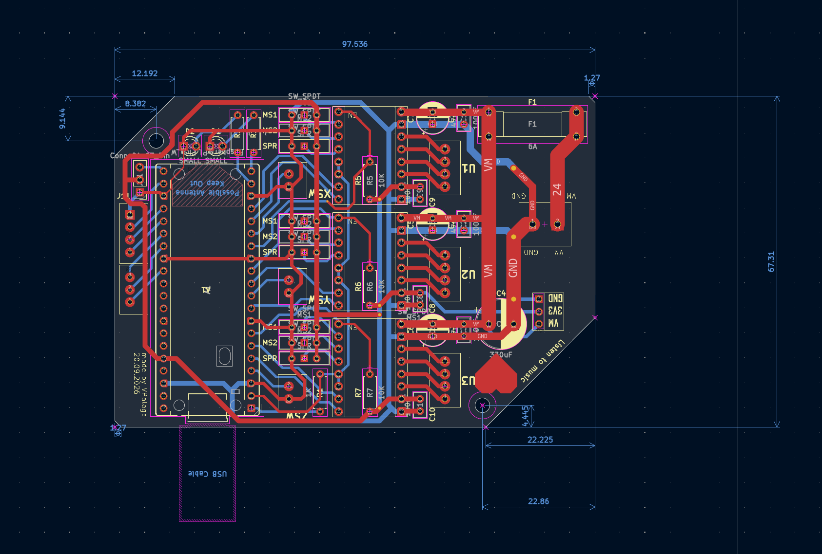
pcb/2.0/DrawMv2.0/pcb2_0_schematic.pdfThe v1 prototype in pcb/test/ is no longer used and is kept only for reference. The *-backups folders are KiCad's automatic backups.
| Qty | Value | Footprint | References |
|---|---|---|---|
| 9 | SW_SPDT | own1:SW_Slide-03_Wuerth-WS-SLTV_10x2.5x6.4_P2.54mm_ok | MS1, MS1, MS1, MS2, MS2, MS2, SPR, SPR, SPR |
| 6 | 100nF | Capacitor_THT:C_Disc_D5.0mm_W2.5mm_P2.50mm | C1, C2, C3, C8, C9, C10 |
| 3 | 10K | Resistor_THT:R_Axial_DIN0207_L6.3mm_D2.5mm_P7.62mm_Horizontal | R5, R6, R7 |
| 3 | 47uF | Capacitor_THT:CP_Radial_D6.3mm_P2.50mm | C5, C6, C7 |
| 3 | ~ | own:TMC2209 | U1, U2, U3 |
| 2 | SMALL | LED_THT:LED_D3.0mm | D1, D2 |
| 2 | ~ | Resistor_THT:R_Axial_DIN0207_L6.3mm_D2.5mm_P7.62mm_Horizontal | R2, R3 |
| 1 | 1K | Resistor_THT:R_Axial_DIN0207_L6.3mm_D2.5mm_P7.62mm_Horizontal | R1 |
| 1 | 330uF | Capacitor_THT:CP_Radial_D10.0mm_P5.00mm | C4 |
| 1 | 6A | Fuse:Fuseholder_Clip-5x20mm_Bel_FC-203-22_Lateral_P17.80x5.00mm_D1.17mm_Horizontal | F1 |
| 1 | Conn_01x03_Pin | Connector_PinHeader_2.54mm:PinHeader_1x03_P2.54mm_Vertical | J11 |
| 1 | Conn_01x03_Pin | own1:XH3pin | J8 |
| 1 | Conn_01x04_Pin | own1:XH4pin | J9 |
| 1 | M1 | own1:4pinTerminal | J1 |
| 1 | M2 | own1:4pinTerminal | J2 |
| 1 | M3 | own1:4pinTerminal | J3 |
| 1 | PWR | own1:Untitled | J4 |
| 1 | RaspberryPi_Pico_W | Module:RaspberryPi_Pico_Common_THT | A1 |
| 1 | X_SW | own1:XH2pin | J5 |
| 1 | Y_SW | own1:XH2pin | J6 |
| 1 | Z_SW | own1:XH2pin | J7 |
| 1 | debug | own1:debug | J10 |
It measures 97.5 × 67.3 mm and has 2 copper layers, 1.6 mm thick.
43 parts. The full list of its parts is on this page, with links to each part's symbol and footprint where PCBKit's library has them.
From the vpalaga/DrawMachine repository on GitHub, at the commit this page was made from: the board is pcb/2.0/DrawMv2.0/DrawMv2.0.kicad_pcb and its schematic pcb/2.0/DrawMv2.0/DrawMv2.0.kicad_sch. PCBKit opens the board in the browser, with nothing to install.
Its repository states no licence, so its author keeps all rights: ask vpalaga before reusing the design.
google/mozc-devices
Circuit diagrams and firmware source code for Gboard DIY keyboards

rusefi/rusefi
rusefi - GPL internal combustion engine control unit


jrsteensen/OpenHornet
OpenHornet 1:1 F/A-18C Simulator Repository


tebl/RC6502-Apple-1-Replica
An expandable SBC-version of the Apple 1 computer, easy to get started with and lot of cool stuff that can be added to it!

nodestark/mdb-esp32-cashless
ESP32-based MDB cashless device for vending machines, supporting EVA DTS DEX/DDCMP telemetry and payments over the MDB protocol via Bluetooth and MQTT

zynthian/zynthian-hw
Zynthian hardware stuff: PCBs, schemes, parts specifications, pin assignment, ...