2 layers65 × 30 mm
Rgb to hdmi
hoglet67/RGBtoHDMI
Bare-metal Raspberry Pi project that provides pixel-perfect sampling of Retro Computer RGB/YUV video and conversion to HDMI
36 parts1kGPL-3.0

 vlinGit/Macropad
A custom macropad utilizing the Raspberry Pi Pico
Macropad is an open-source printed circuit board by vlinGit, from the vlinGit/Macropad repository on GitHub. It is a 2-layer board of 111.9 × 77.8 mm with 36 parts on 59 nets, routed with 158 tracks and 0 vias.
Its parts include 16 diodes, 1 resistor and 1 IC. It belongs with the keyboards and input boards and the RP2040 boards of this library.
Greetings, It seems you've stubbled upon my macropad project :)! Utilizing everything provided from this repo (with a few exceptions) you should be able to make this simple 4x4 macropad using a Pi Pico:
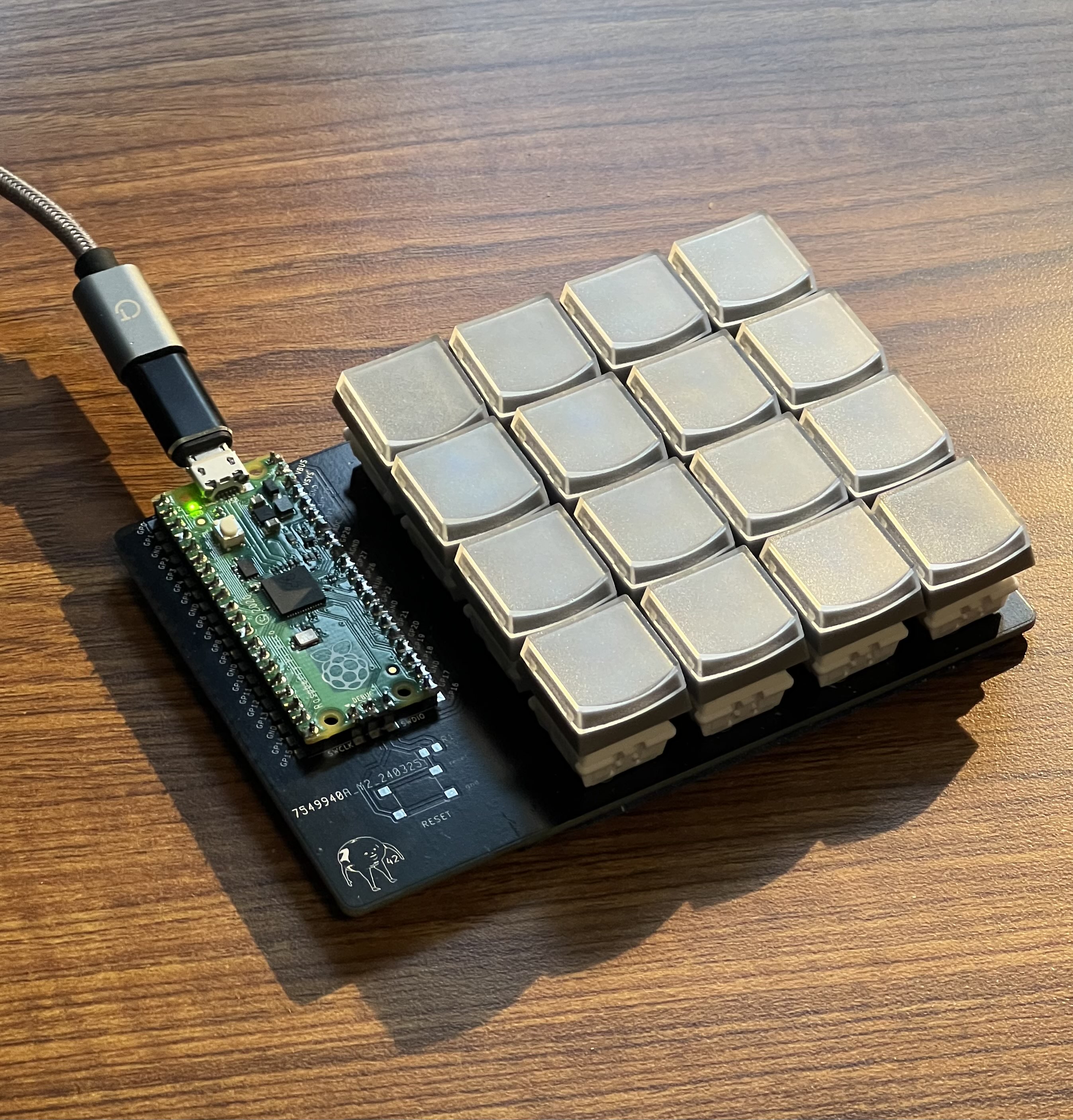
Now I must set some ground rules and mentions those exceptions from the previous text. This repo assumes you have knowledge of:
The next two sections will discuss what the two folders, Macropad and Firmware, in this project do.
All the project files (schematic, pcb, and fingerprints) should be in this folder. When opening this within Kicad, you will most likely need to reassign the location of the fingerprints.
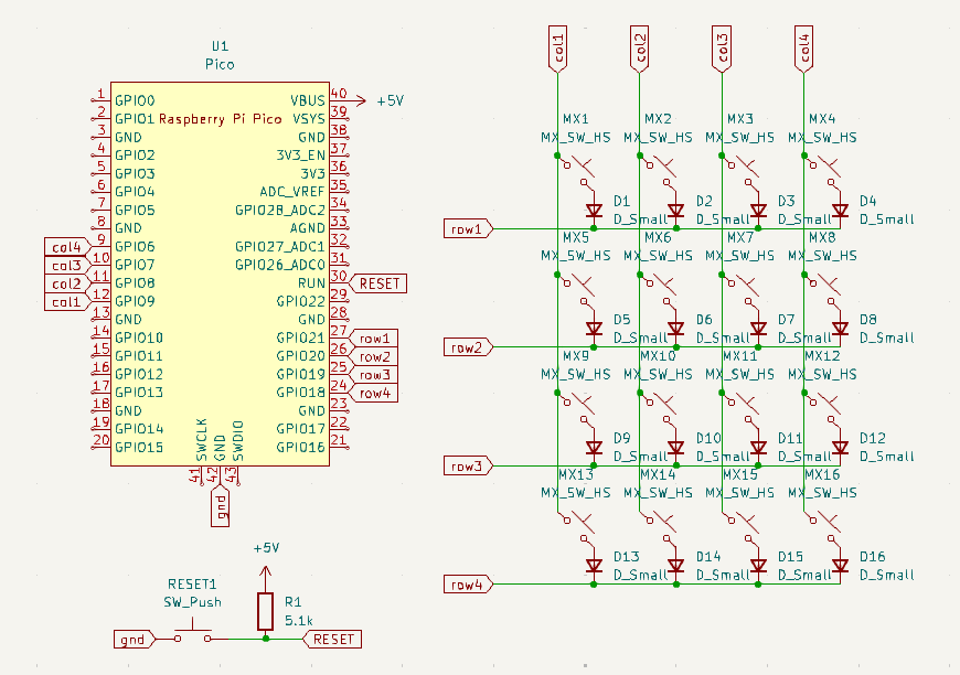
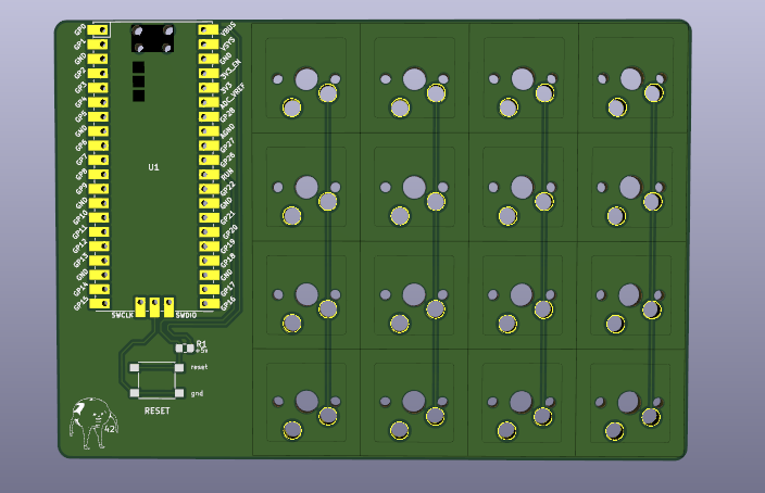
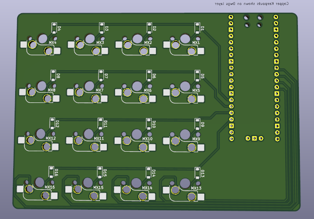
Here's a spreadsheet containing all the items I used. This spreadsheet doesn't include headers, switches, and keys as I already had these lying around.
Sidenote, I left a place for a reset button for convinence, however, this proved to be the complete opposite. The small button got in the way more often than not so the final build doesn't include it.
You will find a lib folder as well as a code.py file in here. The lib folder contains the necessary adafruit library needed for the python file code.py which contains the actual firmware code. These files should be dragged into your Pi Pico after you've installed CircuitPython.
The macropad is designed in a 4x4 matrix with the following pins:
The current python file provides you with two modes:
The modes will be presented in tables, each cell being a key. Every cell labeled null means the key is unassigned. Within the actual code this is represented with a -1.
| VOLUME DECREMENT | VOLUME INCREMENT | MUTE VOLUME | CHANGE MODE |
| PREVIOUS TRACK | PLAY/PAUSE MEDIA | NEXT TRACK | null |
| null | null | null | null |
| null | null | null | null |
| LEFT SHIFT | F14 | F15 | CHANGE MODE |
| F13 | F17 | F18 | F19 |
| F16 | F21 | F22 | F23 |
| LEFT CONTROL | F20 | null | SPACE |
So, whats planned for the future? I've been using this macropad for a couple days now and here's the following things I plan on implementing soon:
As to what I will remove:
| Qty | Value | Footprint | References |
|---|---|---|---|
| 16 | D_Small | Diode_SMD:D_SOD-123 | D1, D2, D3, D4, D5, D6, D7, D8, D9, D10, D11, D12, D13, D14, D15, D16 |
| 16 | MX_SW_HS | marbastlib-mx:SW_MX_HS_CPG151101S11_1u | MX1, MX2, MX3, MX4, MX5, MX6, MX7, MX8, MX9, MX10, MX11, MX12, MX13, MX14, MX15, MX16 |
| 1 | 5.1k | Resistor_SMD:R_0805_2012Metric_Pad1.20x1.40mm_HandSolder | R1 |
| 1 | LOGO | LOGO | 42 |
| 1 | Pico | MCU_RaspberryPi_and_Boards:RPi_Pico_SMD_TH | U1 |
| 1 | SW_Push | Button_Switch_SMD:SW_SPST_PTS645 | RESET |
It measures 111.9 × 77.8 mm and has 2 copper layers, 1.6 mm thick.
36 parts. The full list of its parts is on this page, with links to each part's symbol and footprint where PCBKit's library has them.
From the vlinGit/Macropad repository on GitHub, at the commit this page was made from: the board is MacroPad/MacroPad.kicad_pcb and its schematic MacroPad/KiCad-RP-Pico-main/KiCad-RP-Pico-main/Test/Test.kicad_sch. PCBKit opens the board in the browser, with nothing to install.
Its repository states no licence, so its author keeps all rights: ask vlinGit before reusing the design.
hoglet67/RGBtoHDMI
Bare-metal Raspberry Pi project that provides pixel-perfect sampling of Retro Computer RGB/YUV video and conversion to HDMI

hackclub/OnBoard
💡 Join 1,000 teenagers and make your first PCB with a $100 grant!


tardate/LittleArduinoProjects
a collection of "Little Electronic & Arduino Projects", most involving electronics or an Arduino in one way or another!


Neumi/open_echo
Open Source echo sounder / depth sounder / SONAR for bathymetry and research. Arduino based and compatible.

