2 layers20.5 × 24.8 mm

 vishalbodkhe/LDR-Automatic-Light-Control-PCB
LDR-based automatic light control system with custom KiCad PCB design, DRC verification, Gerber files and 3D visualization.
LDR Automatic Light Control PCB is an open-source printed circuit board by vishalbodkhe, from the vishalbodkhe/LDR-Automatic-Light-Control-PCB repository on GitHub. It is a 2-layer board of 53 × 23 mm with 8 parts on 5 nets, routed with 28 tracks and 0 vias.
Its parts include 3 resistors, 2 connectors, 1 capacitor, 1 diode and 1 transistor.
A custom PCB designed for automatic light control using an LDR sensor.
This project detects ambient light using an LDR and automatically controls the output based on the light intensity.
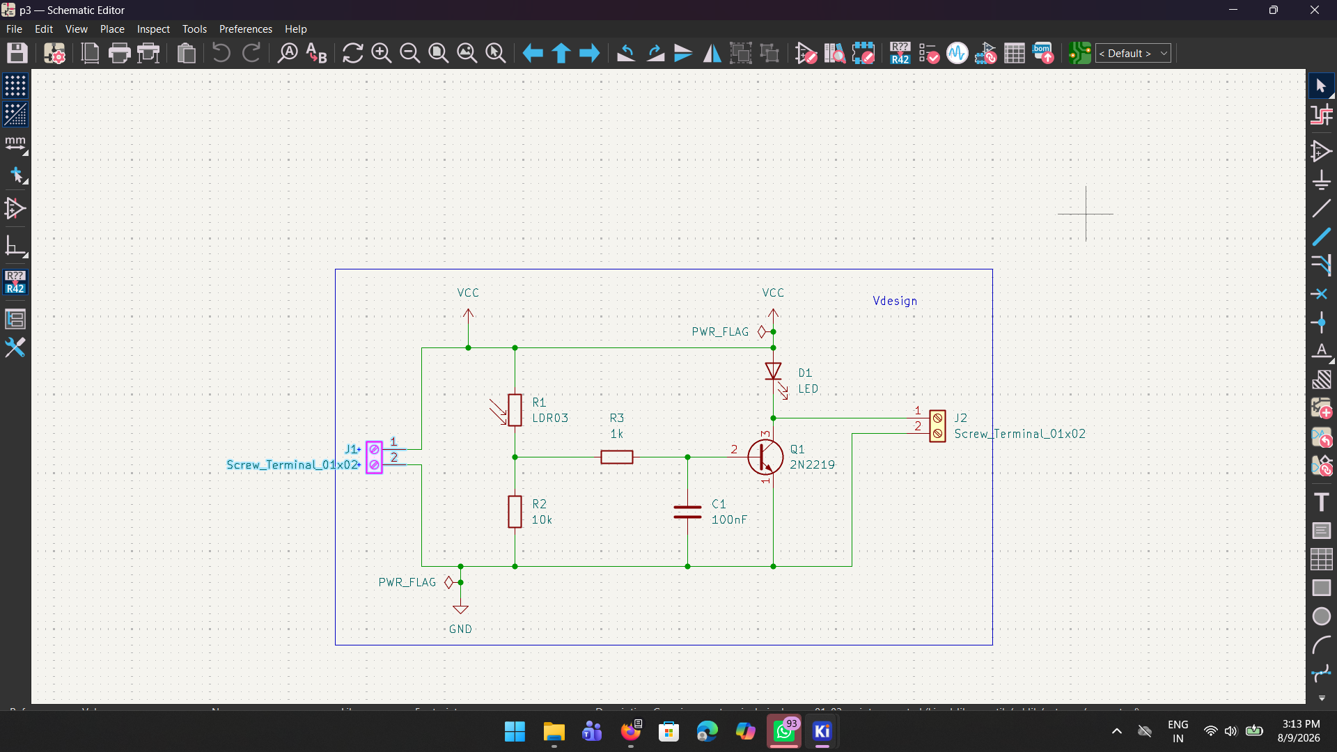
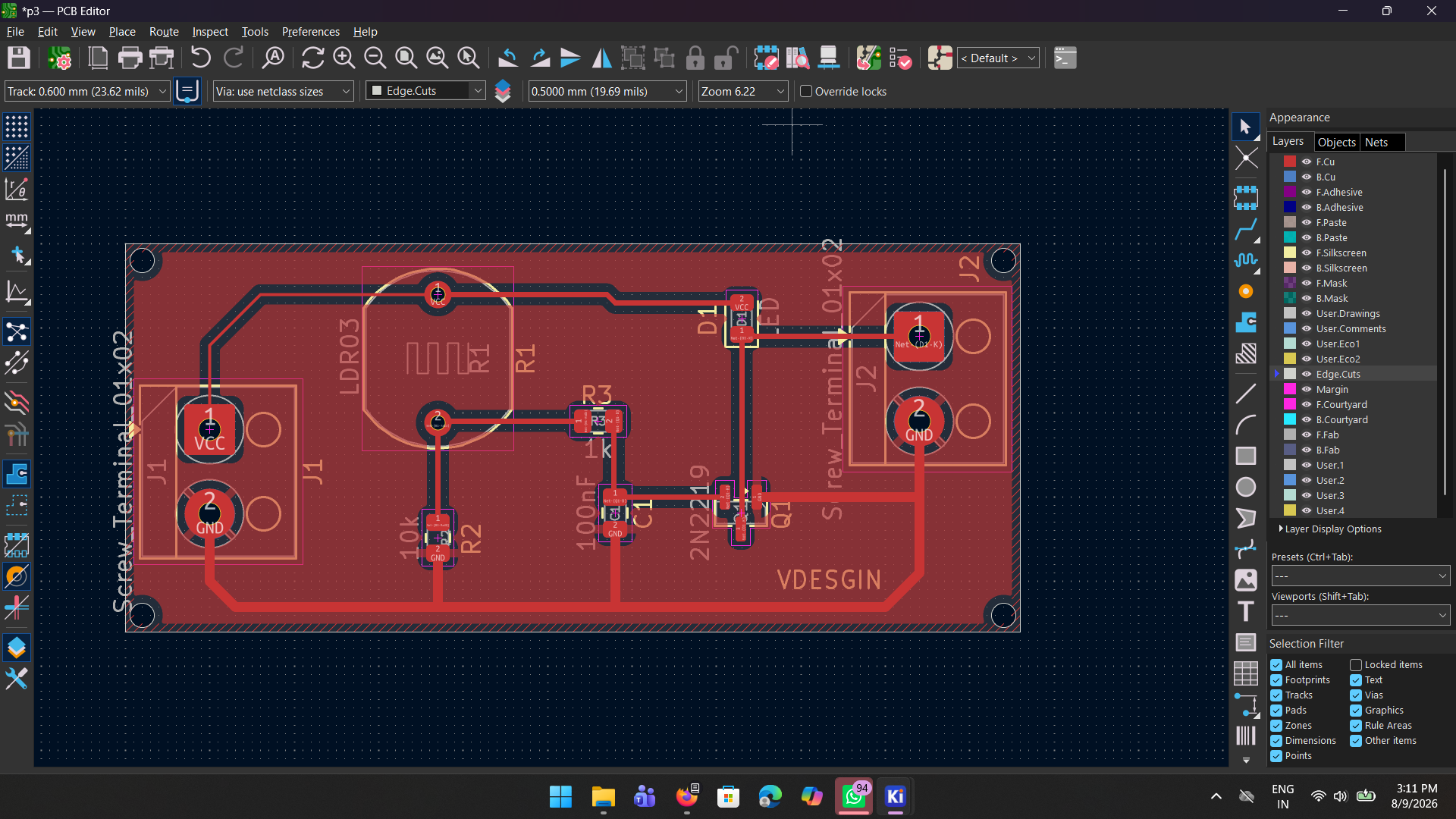
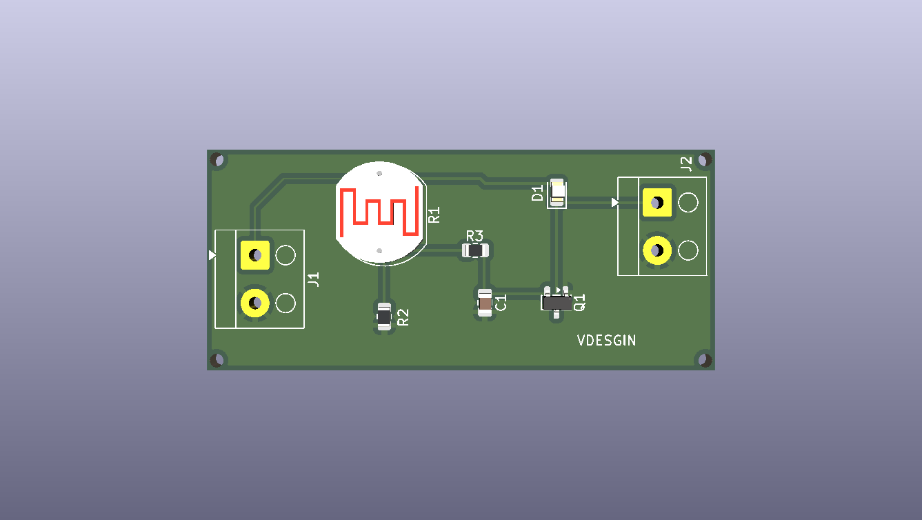
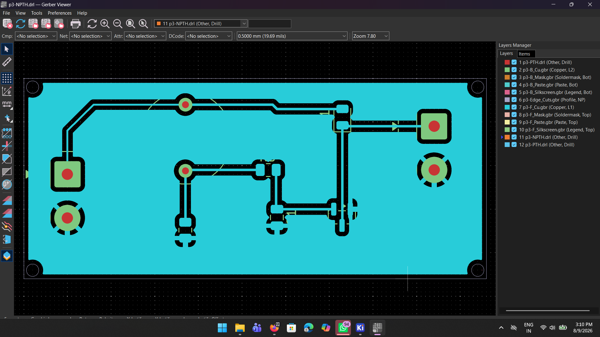
The repository contains:
p3.kicad_sch - Schematicp3.kicad_pcb - PCB Layoutp3.kicad_pro - KiCad ProjectVishal Taterao Bodkhe
Electronics & Computer Engineering
| Qty | Value | Footprint | References |
|---|---|---|---|
| 2 | Screw_Terminal_01x02 | TerminalBlock_Altech:Altech_AK100_1x02_P5.00mm | J1, J2 |
| 1 | 100nF | Capacitor_SMD:C_0805_2012Metric | C1 |
| 1 | 10k | Resistor_SMD:R_0805_2012Metric | R2 |
| 1 | 1k | Resistor_SMD:R_0805_2012Metric | R3 |
| 1 | 2N2219 | Package_TO_SOT_SMD:SOT-23 | Q1 |
| 1 | LDR03 | OptoDevice:R_LDR_10x8.5mm_P7.6mm_Vertical | R1 |
| 1 | LED | LED_SMD:LED_0805_2012Metric | D1 |

joeycastillo/Sensor-Watch
A board replacement for the classic Casio F-91W wristwatch

rusefi/rusefi
rusefi - GPL internal combustion engine control unit

hoglet67/RGBtoHDMI
Bare-metal Raspberry Pi project that provides pixel-perfect sampling of Retro Computer RGB/YUV video and conversion to HDMI

shanteacontrols/OpenDeck
A platform for building interactive control and sensing devices using MIDI and OSC built with Zephyr RTOS.

hackclub/OnBoard
💡 Join 1,000 teenagers and make your first PCB with a $100 grant!

dangiu/PicoMemcard
Emulating PSX Memory Card (or controller) using a Raspberry Pi Pico

OLIMEX/DIY-LAPTOP
Do It Yourself Open Source Hardware and Software Modular Hacker's Friendly Laptop
It measures 53 × 23 mm and has 2 copper layers, 1.6 mm thick.
8 parts. The full list of its parts is on this page, with links to each part's symbol and footprint where PCBKit's library has them.
From the vishalbodkhe/LDR-Automatic-Light-Control-PCB repository on GitHub, at the commit this page was made from: the board is p3.kicad_pcb and its schematic p3.kicad_sch. PCBKit opens the board in the browser, with nothing to install.
Its repository states no licence, so its author keeps all rights: ask vishalbodkhe before reusing the design.