
2 layers137.2 × 83.8 mm
PWA REV2
PubInv/krake
The Krake™ is a Wi-Fi–enabled server using an MQTT broker, which means it can be controlled remotely by other devices ("clients") via the internet.
215 parts9AGPL-3.0

 Vihaan6119/AURA
AURA is a custom 75% mechanical keyboard designed and built from the ground up for coding, typing, and gaming. It will feature Bluetooth connectivity, USB-C, hot-swappable switches, RGB lighting, a programmable rotary knob, media and lock controls, a rechargeable battery, and a solid, premium enclosure.
AURA is an open-source printed circuit board by Vihaan6119, from the Vihaan6119/AURA repository on GitHub. It is a 2-layer board of 85.6 × 100 mm with 13 parts on 36 nets, routed with 110 tracks and 13 vias.
It is built around the EC11E18244AU. Its parts include 7 switches and 1 IC. It belongs with the lEDs and displays boards and the RP2040 boards of this library.
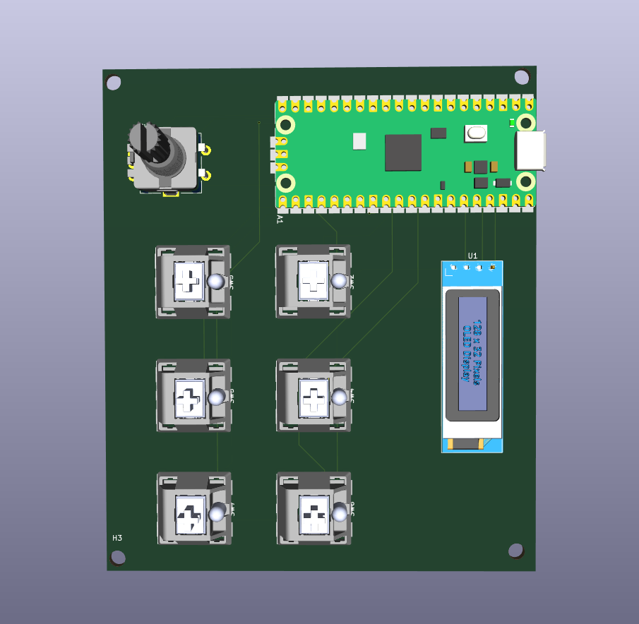
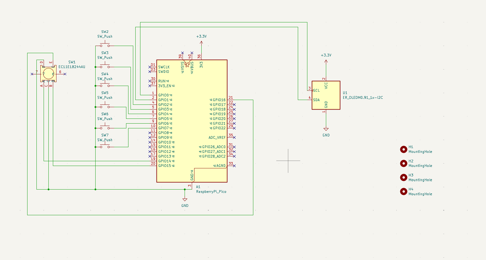
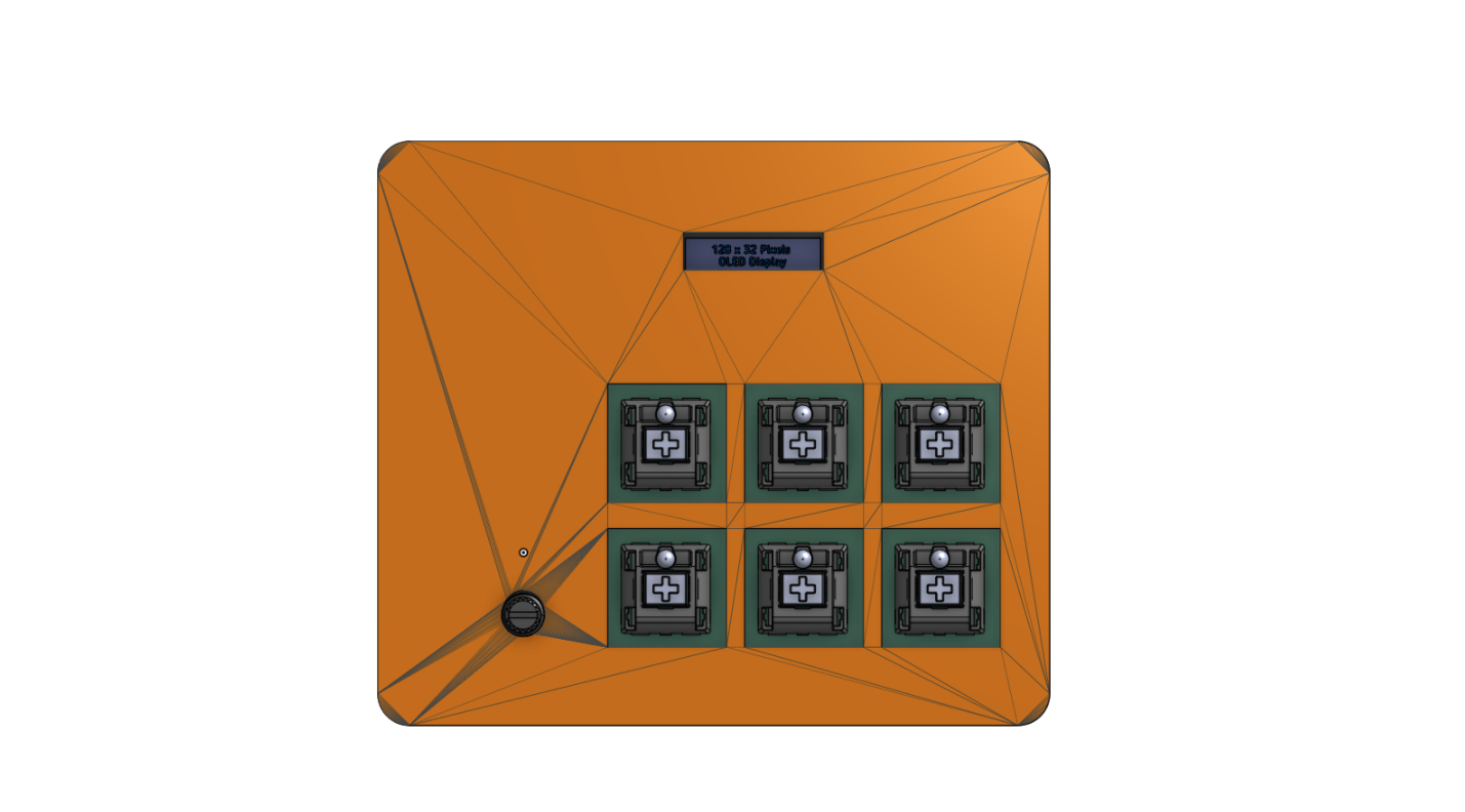
AURA is a custom mechanical desktop controller designed for media navigation and other things basic need in my life. It is built around a Raspberry Pi Pico, it has 6 mechanical keys, an 0.91 inch OLED display, and a multi-function rotary knob.
In simple words, I have made a PCB which has the neccessary areas and cutout (inside the PCB) to solder the parts in.
Here the Rasberry Pi Pico works as the main controller of this project which handels all the working from presseng the switches, turning the knob to the text in the display. It controls almost everything.
For the controls I have used the Key which will help me do a the kind of shortcut which i like to have on it.
The knob is there for the up/down scrolling and the left/right scrolling in PDFs, webpages, CAD apps, 3D modeling, volume control, etc.
The display is for showing wither the time or the current sony which is being play, with basic info in it. (this can also be coustomised from the firmware of the project).
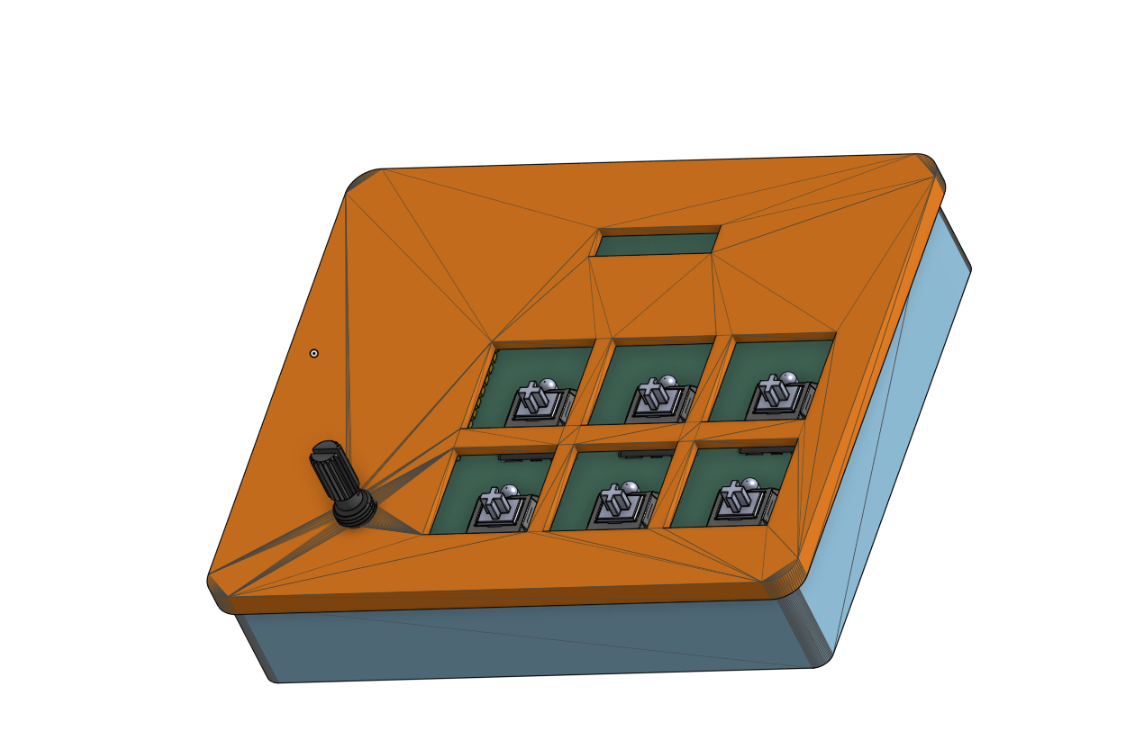
I have specially designed a coustom enclosure for this, which is in 2 parts.
Base part: Here is where the PCB will be sitting. It will be mounted securly by the M3 mounting holes. There is a cutout on the back side of the Base so that we can connect the power/data cable to the Rasberry Pi Pico.
Top Lid: The lid will be placed on the base lid securly. There are required cutouts for the display, the keys and the knob.
I have made the colour of base as the default color, and the top in orange color to differential between them and make it easier for me to make and assemble the full enclosure with the PCB and all the parts. In the final printing, the enclosure will have a black colour (from the black PLA filament from the printing legion).
The .step file of the PCB is in the folder namedHardware. The name of the exact file is AURA V2.step The rest of the file are in the folder named Enclosure.
The base part is of the name AURA base.step. The top Lid is of the name AURA lid.step. The complete assembly of the enclosure with the PCB is of the name AURA Full Assembly.step.
Unfortunatily, there is a specify way in which you have to open the AURA Full Assembly.step to actully get the the fully assembled file which has the base, top lid and the PCB with all the parts.
This is the way (for this I am using Onshape. I think it will almost similar for all the different softwares):

SW2 through SW7).config.json file stored directly on the device.H1–H4) for robust case assembly.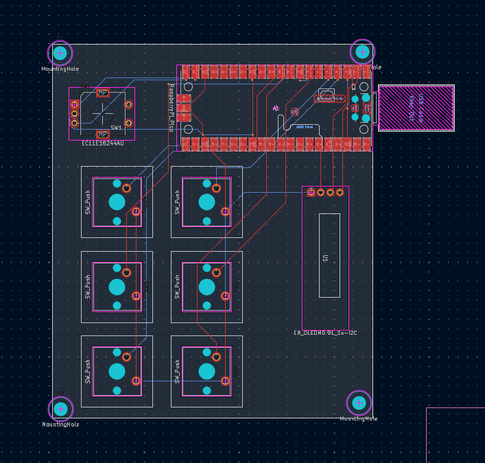
| Item | Qty | Supplier | Cost/item | Total Cost | Link |
|---|---|---|---|---|---|
| Raspberry Pi Pico | 1 | besomi | $8.00 | $8.00 | Link |
| SSD1306 OLED Display (0.91") | 1 | AliExpress | $1.23 | $1.23 | Link |
| EC11 Rotary Encoder with Switch | 1 | LCSC | $2.22 | $2.22 | Link |
| Cherry MX Mechanical Switches | 10 | AliExpress | $0.71 | $7.10 | Link |
| M3 Screws and Standoffs Set | 30 | ALiExpress | $0.12 | $3.60 | Link |
| Custom PCB (AURA) | 5 | JLC PCB | $0.80 | $4.00 | Link |
| Estimated total shipping | 1 | Printing Legion | $3.00 | $3.00 | Link |
Tax & shipping: $15.59
Total: $44.75
| Qty | Value | Footprint | References |
|---|---|---|---|
| 6 | SW_Push | Button_Switch_Keyboard:SW_Cherry_MX_1.00u_PCB | SW2, SW3, SW4, SW5, SW6, SW7 |
| 4 | MountingHole | MountingHole:MountingHole_3.2mm_M3 | H1, H2, H3, H4 |
| 1 | EC11E18244AU | Rotary_Encoder:RotaryEncoder_Alps_EC11E-Switch_Vertical_H20mm | SW1 |
| 1 | ER_OLEDM0.91_1x-I2C | Display:ER_OLEDM0.91_1x-I2C | U1 |
| 1 | RaspberryPi_Pico | Module:RaspberryPi_Pico_SMD_HandSolder | A1 |
PubInv/krake
The Krake™ is a Wi-Fi–enabled server using an MQTT broker, which means it can be controlled remotely by other devices ("clients") via the internet.

JDPennockGB/ENGR357-SDR-PennockRoque
A custom-built, high-performance Software Defined Radio (SDR) receiver powered by the Raspberry Pi Pico (RP2040).

AronTech1/Galatea-75-wireless-mechanical-keyboard
Galatea: 75% wireless mechanical keyboard with a 5" IPS display, per-key LEDs, rotary encoder, voice button and I²S microphone.


NEOgHacking/DMXion_4Port_Node
A 4 port dmx node with rdm funtionallity. Connects via ARTNET or sACN


samyk/magspoof
A portable device that can spoof/emulate any magnetic stripe, credit card or hotel card "wirelessly", even on standard magstripe (non-NFC/RFID) readers.
It measures 85.6 × 100 mm and has 2 copper layers, 1.6 mm thick.
13 parts, built around the EC11E18244AU. The full list of its parts is on this page, with links to each part's symbol and footprint where PCBKit's library has them.
From the Vihaan6119/AURA repository on GitHub, at the commit this page was made from: the board is Hardware/AURA.kicad_pcb and its schematic Hardware/AURA.kicad_sch. PCBKit opens the board in the browser, with nothing to install.
Its repository states no licence, so its author keeps all rights: ask Vihaan6119 before reusing the design.