

2 layers99.1 × 99.7 mm
RC6502 General Video Adapter
tebl/RC6502-Apple-1-Replica
An expandable SBC-version of the Apple 1 computer, easy to get started with and lot of cool stuff that can be added to it!
80 parts193GPL-3.0

 vich-667/OptolinkDuoBlock2
This project was created to have local access to the viessmann heating system to monitor and control and have the vitoconnect still working.
OptolinkDuoBlock is an open-source printed circuit board by vich-667, from the vich-667/OptolinkDuoBlock repository on GitHub, published under the MIT licence. It is a 2-layer board of 142.2 × 52.1 mm with 35 parts on 25 nets, routed with 84 tracks and 10 vias.
It is built around the BAT42, BC547 and SFH 309. Its parts include 9 resistors, 6 diodes, 6 transistors, 4 connectors and 2 capacitors.
This project was created to have local access to the viessmann heating system to monitor and control and have the vitoconnect still working. In OpenV Wiki and it's issue section can be found a lot of information and links to other interesting Projects. But all of them either only monitor the communication between the heating system and the vitoconnect or the directly communicate with the heating system. Therefore, this project was started to control the connection of the vitoconnect from the monitoring pc.
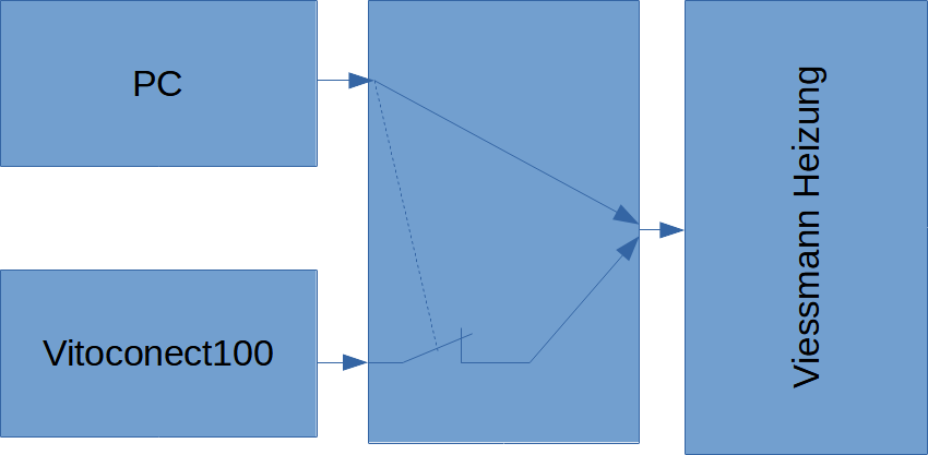
The basic idea of this project was taken from USB_Duo-Sniffer. I extended the circuit to be able to block the vitoconnect to be able to send read or write commands directly to the heating system.
Finally, the heatpump should be integrated into my OpenHAB installation to monitor the status and control it depending on PV power and weather situation. Due to the reason I'm not very familiar with Java (and the long delay of PR reviews) I wrote the Software with Python and reused a simple HTTP Server from another Project to integrate it into OpenHABs via the http plugin. So this Project can be also reused in other context.
| Folder | Content |
|---|---|
| Datasheet | Datasheets of used components |
| PCB | Schematic and PCP design. Created with KiCad |
| Pictures | Pictures of the Optolink Duo Block |
| Simulation | Electrical Simulation with LTSpice |
| Software | Software to monitor and read/write written in Python. |
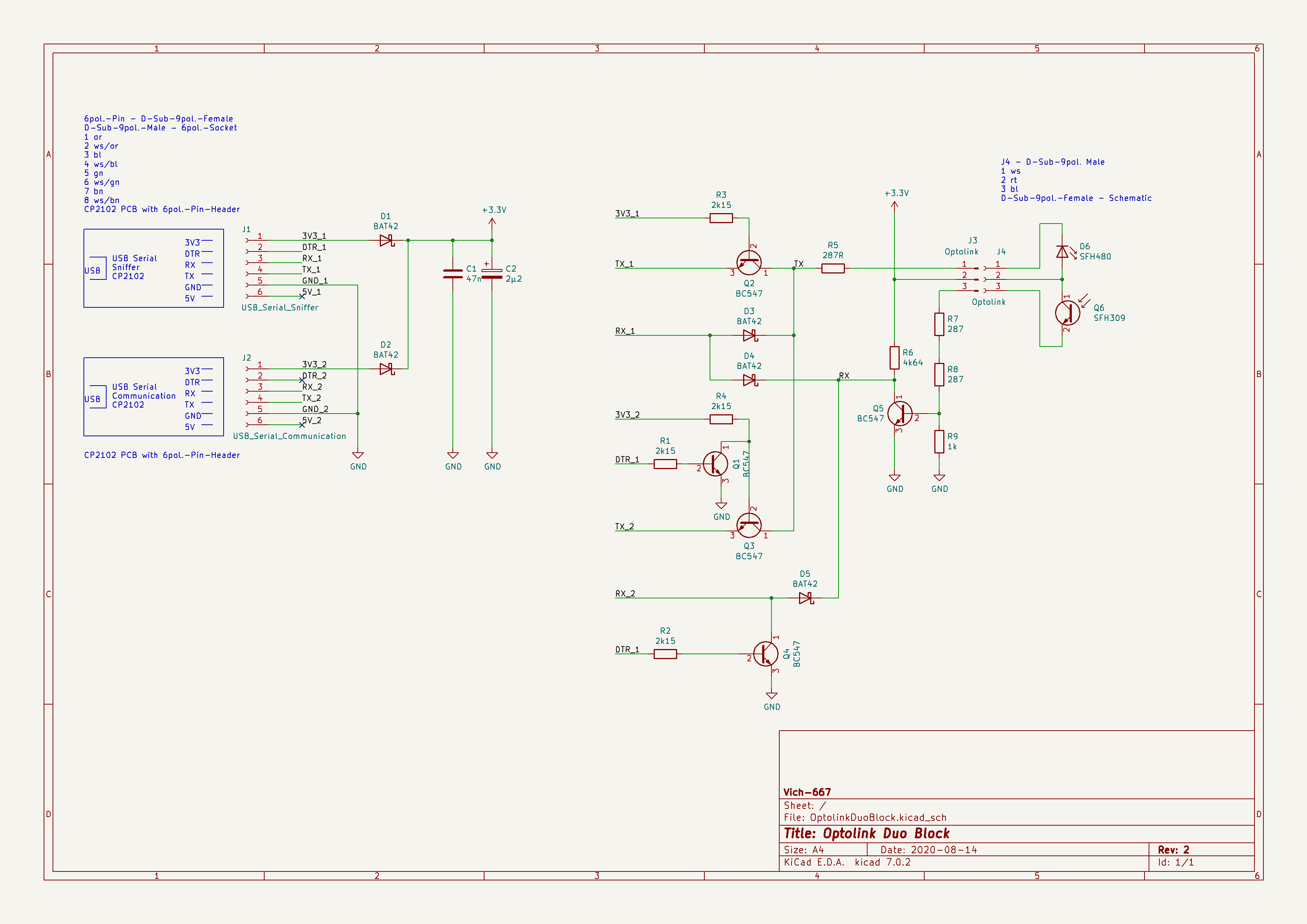 The schematic from USB_Duo-Sniffer
was reused and extended in a way that with the DTR Pin of the sniffer PC the Tx as well the Rx from the Vitoconnect can be blocked. In block mode
read and write messages can be sent directly to the heating system. In unblock mode the vitoconnect can communicate and the communication can be monitored.
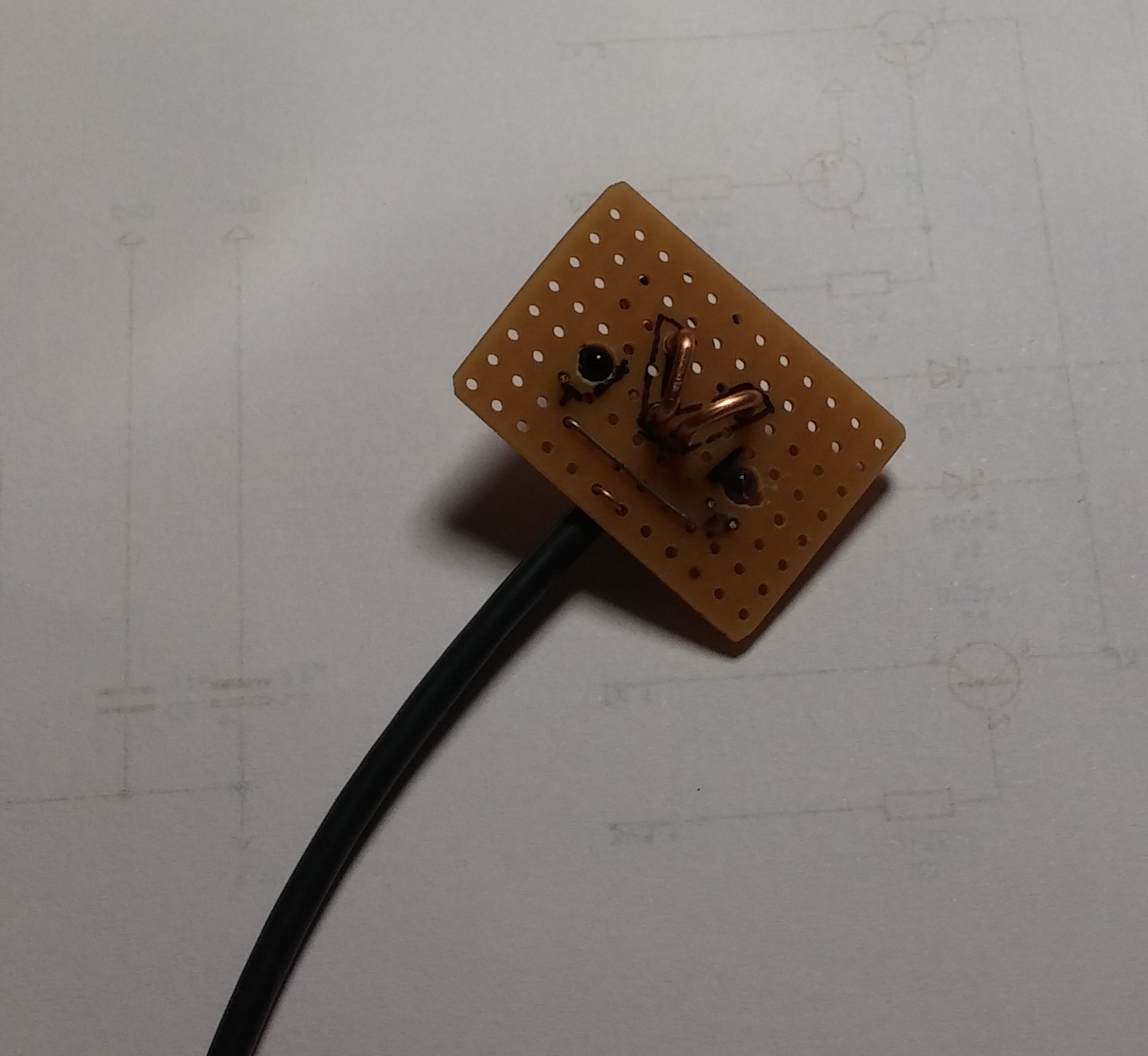
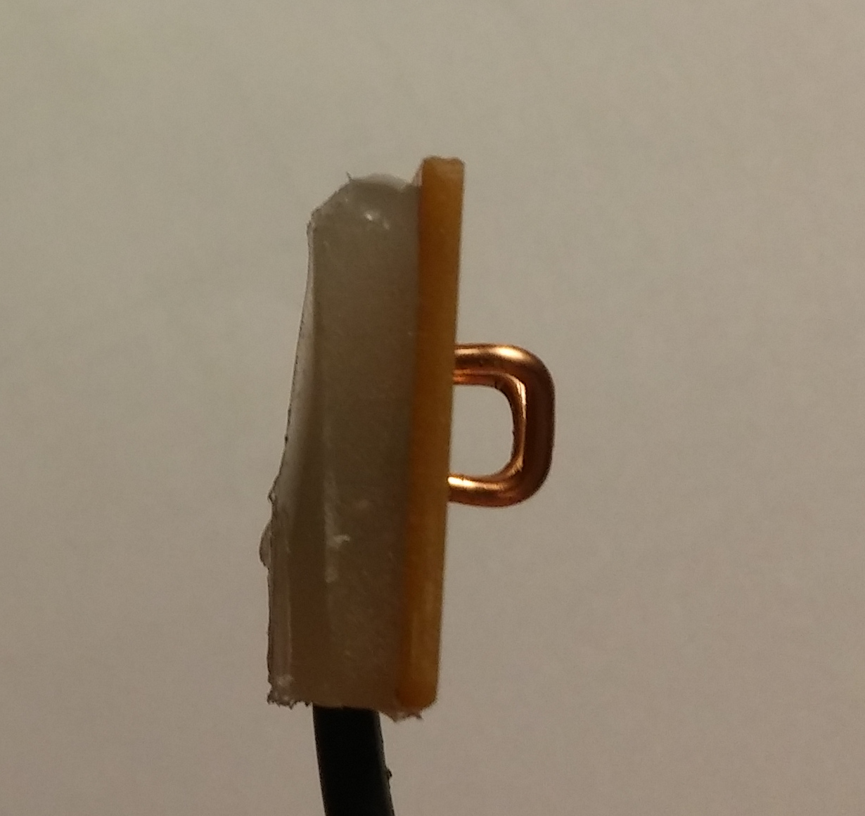 The IR PCB was created in a similar way you can find it in OpenV Wiki
as well. To fit it exact inside the cover, I simply put some tape around it and filled up the backside with
hot glue, that it has nearby the same size as the original.

 The circuit was soldered with TH components. And placed into an additional box. The advantage of this hardware solution over a proxy solution is that the vitoconnect can work
as long the pc is not connected or the DTR pin is low.
The vito_monitor_ctrl is the basic lib (it can be reused in other applications or projects) what provides the VitocalHandler class. This class factor the whole thing and
provides methods to read and write data points.
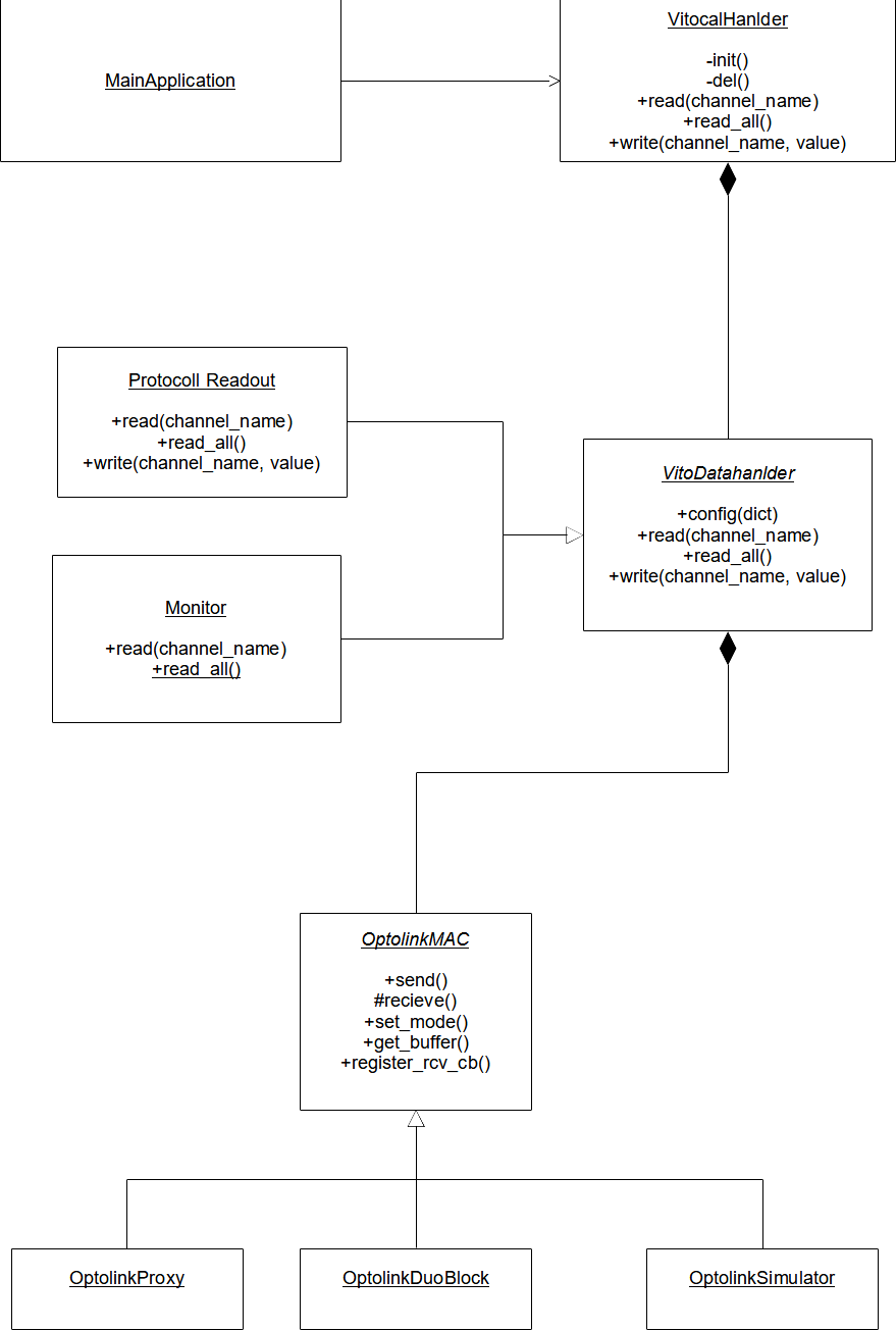 Basically there is the
VitoDatahandler Interface with its two implementation, for monitoring the vitoconnect and the direct read / write access. To not direct deepened on any
hardware there is the OptolinkMAC to abstract them. An implementation for the OptolinkDuoBlock as well as a Dummy for testing without hardware exists. Also a implementation
for the Proxy solution was created, but never tested or used.
Data point to be read and write need to be configured either statically via value_config.py or you can set the dict during runtime. This dict contains the data point names as
key and a parameter dict with fixed names.
"Aussentemperatur": { "address": 0x1234, "unit": "UT", "access": 1 , "description": "anyting, currently unused", "data_bytes": 4 }
| Key | Info |
|---|---|
| address | Address of data point |
| unit | Unit to convert data, see vito_data_handler.py |
| data_bytes | Number of bytes to read / write independent from unit |
| access | Access type: MONITOR = 0x01, READOUT = 0x02, WRITE = 0x04 or any and combination |
| description | Any description, currently not used |
cmd_line_main.py: This application provides a simple shell for testing
w <data_point_name> <value> to write a data pointexit to closehttp_server_main.py: http server to be accessed from any other tools
curl localhost:8006 | jq -Chttp://localhost:8006 or http://localhost:8006/getstatus/ a json object with all current values and system status is providedhttp://localhost:8006/set/vito/<data_point_name> to write the data, the value need to be provided as a plain testhttp://localhost:8006/set/vito/configuration to set the config. It needs to be provided as a json object| Qty | Value | Footprint | References |
|---|---|---|---|
| 5 | BAT42 | Diode_THT:D_DO-35_SOD27_P7.62mm_Horizontal | D1, D2, D3, D4, D5 |
| 5 | BC547 | Package_TO_SOT_THT:TO-92L_Inline_Wide | Q1, Q2, Q3, Q4, Q5 |
| 4 | Connector_Pin:Pin_D1.0mm_L10.0mm | , , , | |
| 4 | MountingHole:MountingHole_3.2mm_M3 | , , , | |
| 4 | 2k15 | Resistor_THT:R_Axial_DIN0207_L6.3mm_D2.5mm_P10.16mm_Horizontal | R1, R2, R3, R4 |
| 2 | 287 | Resistor_THT:R_Axial_DIN0207_L6.3mm_D2.5mm_P10.16mm_Horizontal | R7, R8 |
| 1 | 1k | Resistor_THT:R_Axial_DIN0207_L6.3mm_D2.5mm_P10.16mm_Horizontal | R9 |
| 1 | 287R | Resistor_THT:R_Axial_DIN0207_L6.3mm_D2.5mm_P10.16mm_Horizontal | R5 |
| 1 | 2µ2 | Capacitor_THT:CP_Radial_D5.0mm_P2.50mm | C2 |
| 1 | 47n | Capacitor_THT:C_Disc_D7.5mm_W5.0mm_P7.50mm | C1 |
| 1 | 4k64 | Resistor_THT:R_Axial_DIN0207_L6.3mm_D2.5mm_P10.16mm_Horizontal | R6 |
| 1 | Optolink | Connector_PinSocket_2.54mm:PinSocket_1x03_P2.54mm_Vertical | J4 |
| 1 | Optolink | Connector_PinHeader_2.54mm:PinHeader_1x03_P2.54mm_Vertical | J3 |
| 1 | SFH309 | LED_THT:LED_D3.0mm_Clear | Q6 |
| 1 | SFH480 | Package_TO_SOT_THT:TO-18-2_Window | D6 |
| 1 | USB_Serial_Communication | Connector_PinSocket_2.54mm:PinSocket_1x06_P2.54mm_Vertical | J2 |
| 1 | USB_Serial_Sniffer | Connector_PinSocket_2.54mm:PinSocket_1x06_P2.54mm_Vertical | J1 |
tebl/RC6502-Apple-1-Replica
An expandable SBC-version of the Apple 1 computer, easy to get started with and lot of cool stuff that can be added to it!

simonyiszk/kezfertotlenito.sch
Liftbe szerelhető, alacsony fogyasztású kézfertőtlenítő tervei


www-ShapeLabs-de/sgm4_to_mqtt
ESP8266 electricity meter reading head for SGM-C4 meter with homeassistant mqtt-discovery

chof747/smartmeter-ir-reader
This is an implementation of the smart reader concept created by volkszaehler.org.


xPiTi/pillex-main
Submission files for MSc project - Pillex - pill dispensing device
It measures 142.2 × 52.1 mm and has 2 copper layers, 1.6 mm thick.
35 parts, built around the BAT42, BC547 and SFH 309. The full list of its parts is on this page, with links to each part's symbol and footprint where PCBKit's library has them.
From the vich-667/OptolinkDuoBlock repository on GitHub, at the commit this page was made from: the board is PCB/OptolinkDuoBlock/OptolinkDuoBlock.kicad_pcb and its schematic PCB/OptolinkDuoBlock/OptolinkDuoBlock.kicad_sch. PCBKit opens the board in the browser, with nothing to install.
Its repository publishes it under the MIT licence: you may reuse it on that licence's terms (keep the author's notice, and for a copyleft licence share your changes alike).