2 layers80.2 × 67.9 mm

 via/viaems-boards
ViaEMS PCB Designs
Io v2 is an open-source printed circuit board by via, from the via/viaems-boards repository on GitHub. It is a 2-layer board of 145.5 × 51 mm with 95 parts on 71 nets, routed with 529 tracks and 40 vias.
It is built around the MIC4469BN, MAX9926UAEE+ and LM2940S-5.0, with the BAT54S among its other parts. Its parts include 50 resistors, 13 connectors, 12 capacitors, 8 transistors and 5 ICs.


ViaEMS PCB Designs
In order of creation...
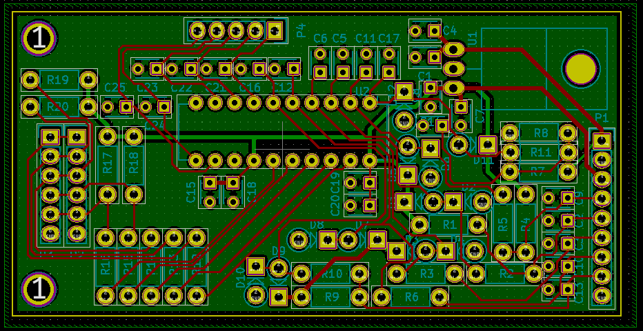
Do not use because:
Original all-in-one board for ViaEMS
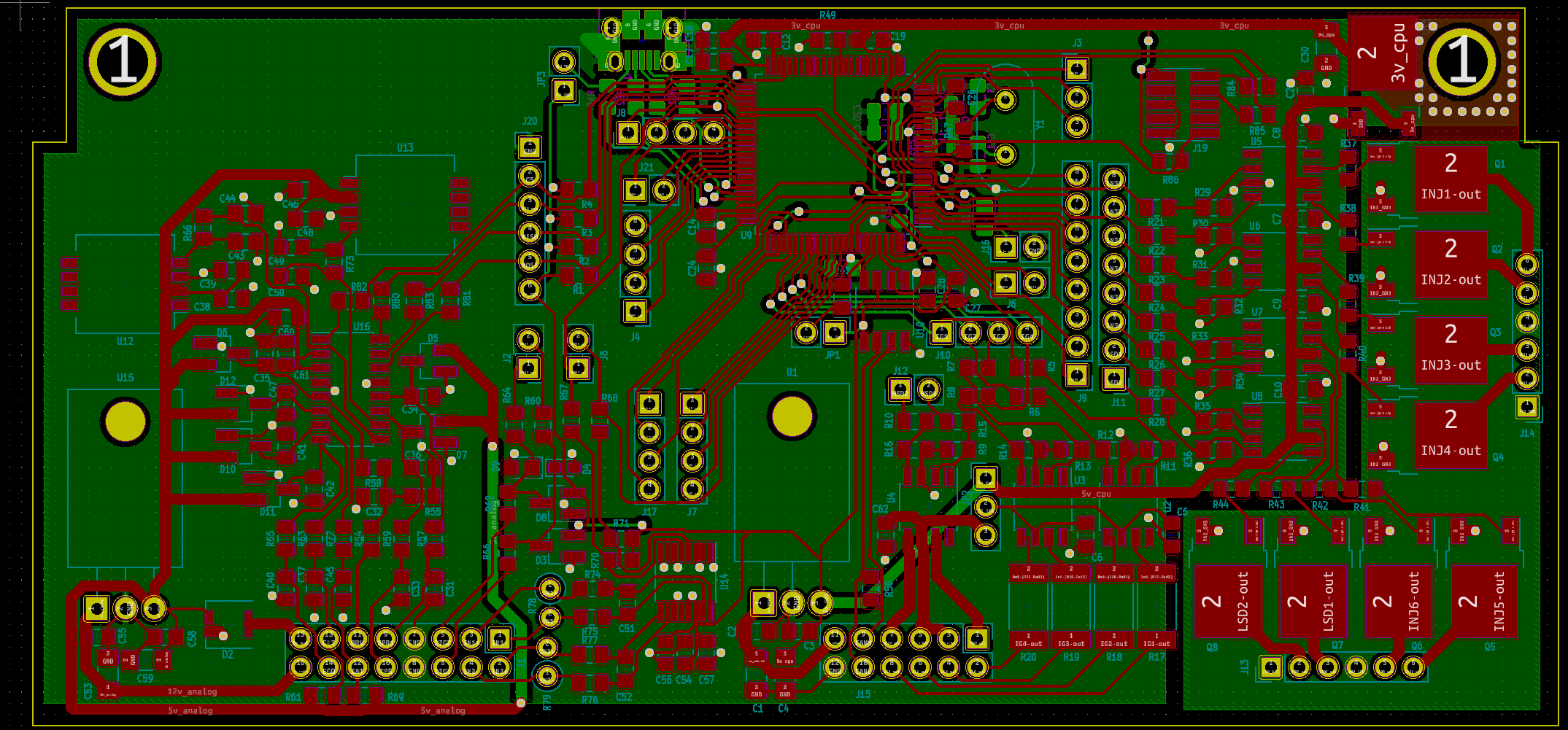
Shouldn't be used anymore, but really only because the outputs chosen for test trigger vs real triggers are different in firmware. The board can be used again with some minor tweaks (and I have used this board for years)
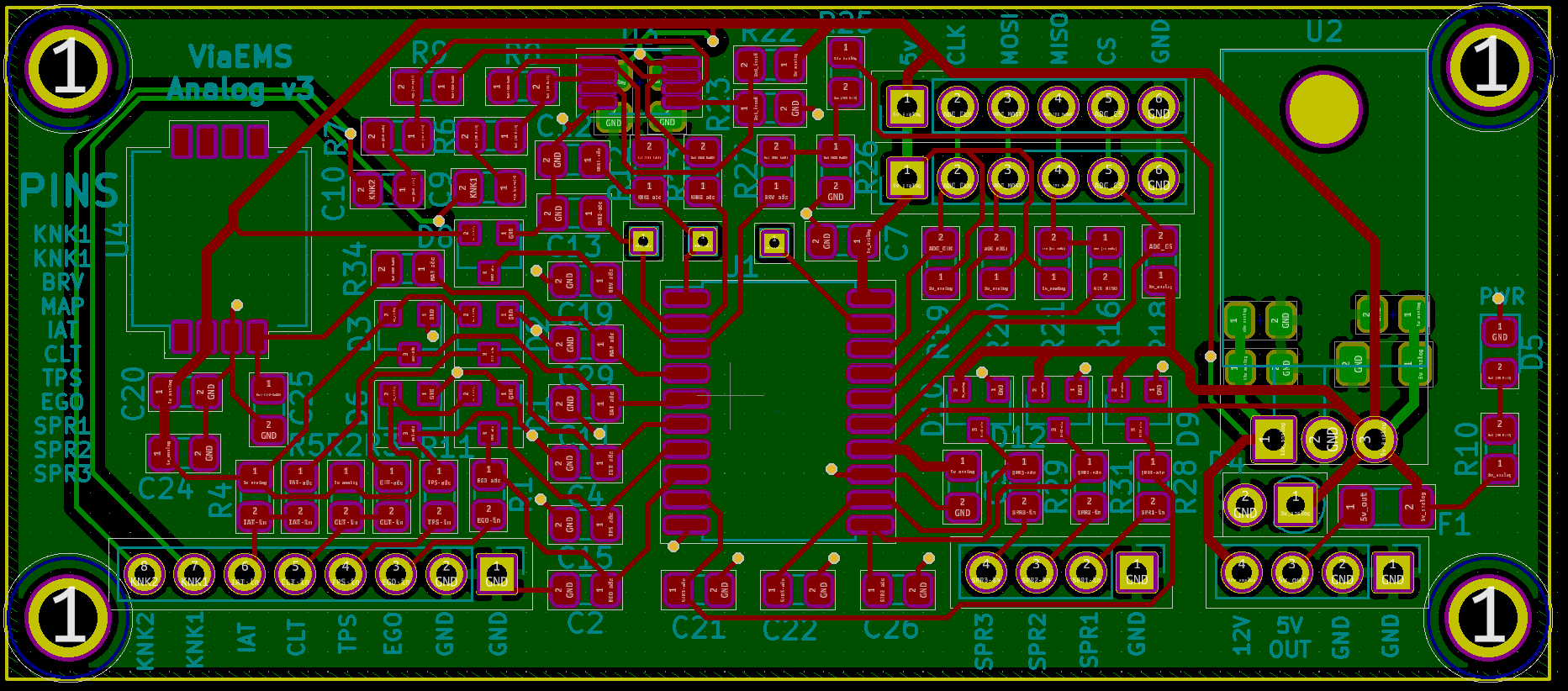
Experiment board to prototype use of the MAX11632, and some knock sensing equipment. The ADC samples fast enough to dedicate two inputs to knock sensing, which uses an op amp input filter. Provides core inputs, a dedicated MAP sensor, and an additional 8 spare inputs.
The board works fine, but I'm unlikely to commit to the MAX11632: since it seems incredibly finicky with SPI noise, and it doesn't provide a good way to know if there is an issue. It requires a setup command. The knock sensing filter works great though. Ultimately issues with this chip pushed me to investigate the TLV2553.
Also, its way too big.
** Do not use! ** Simple breakout board as an upgrade to IO V2:
Experiment with replacing the 2-port gate drivers with the 4-port MIC4469 variant. This board was made mostly to experiment with various FETs.
This board is missing inline resistors between the MIC4469 and FETs. This is incredibly important for the VND7NV04 -- without it, the negative pulse from injectors destroys the gate control logic and causes it to latch partly on.
Ultimately this board is also way too big.
Another experiment, this time for the TI TLV2553. This ADC has only 11 inputs, and samples at 200kHz (vs 300 kHz of the MAX11632). However, its control is identical to the TLC2543, which has self test functionality. It is still fast enough to allow for two inputs to be sampled at 40 kHz (and the rest at 10 kHz).
I decided (after the fact) to make all the other boards the same form factor
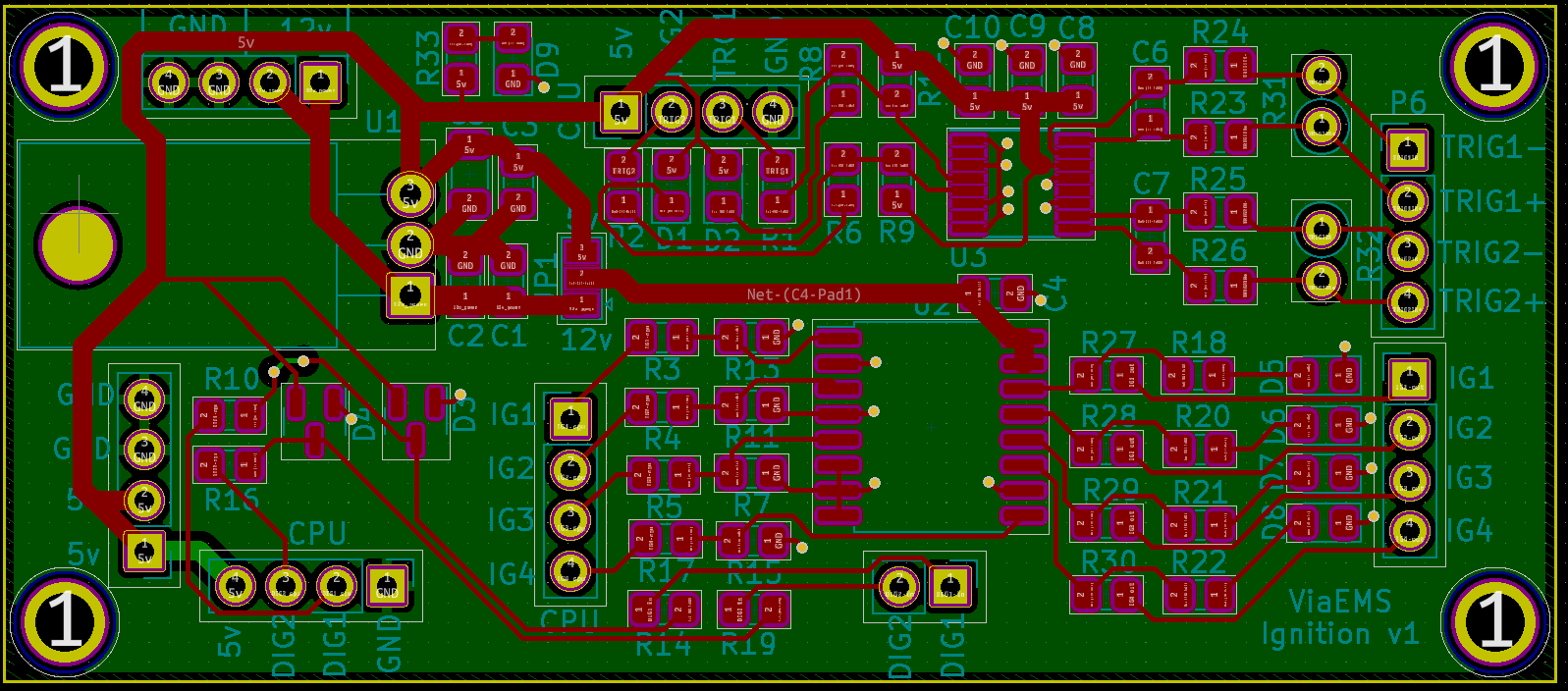
The full contents of IO V2 could not fit on a single 78x34 board, so it is split into two -- one for the low side drivers, one for everything else. Other lessons learned from IO V2 were to add gate resistors for the FETs, and that indicator LEDs are worth the effort to plan into the design.
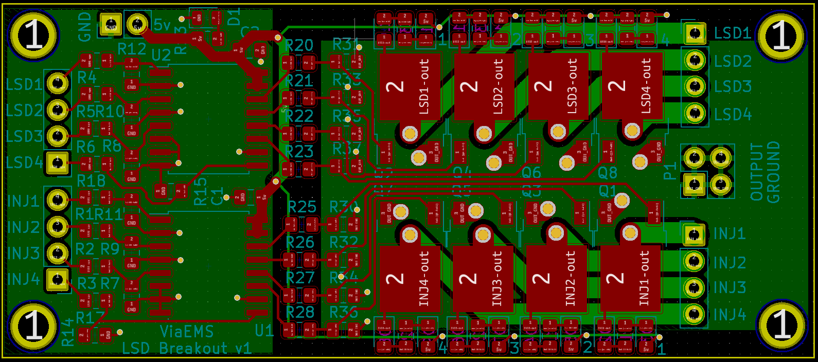
An upgrade from IO V2, with gate resistors fixed, indicator LEDs on all outputs and trigger inputs
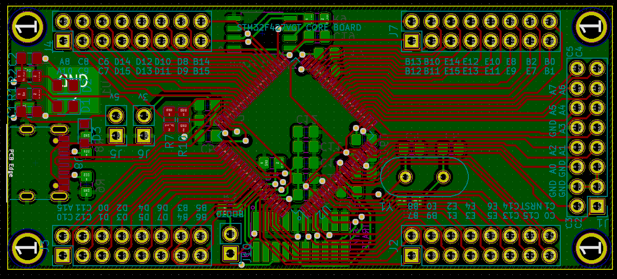
Generic testing board for stm32f427 or gd32f470. This is the same pcb dimensions as the prior 3 boards, and comes with:
| Qty | Value | Footprint | References |
|---|---|---|---|
| 22 | 1k | Resistor_SMD:R_0805_2012Metric_Pad1.20x1.40mm_HandSolder | R1, R2, R3, R12, R18, R19, R20, R21, R22, R23, R24, R35, R36, R37, R38, R39 +6 |
| 20 | 100k | Resistor_SMD:R_0805_2012Metric_Pad1.20x1.40mm_HandSolder | R11, R17, R41, R42, R43, R44, R45, R46, R47, R48, R51, R52, R53, R54, R55, R56 +4 |
| 8 | MOSFET | Package_TO_SOT_SMD:TO-252-2 | Q1, Q2, Q3, Q4, Q5, Q6, Q7, Q8 |
| 4 | 150 | Resistor_SMD:R_0805_2012Metric_Pad1.20x1.40mm_HandSolder | R13, R14, R15, R16 |
| 3 | 1 uF | Capacitor_SMD:C_0805_2012Metric_Pad1.18x1.45mm_HandSolder | C5, C19, C20 |
| 3 | MIC4469 | Package_SO:SOIC-16W_7.5x10.3mm_P1.27mm | U2, U12, U13 |
| 2 | 0.1 uF | Capacitor_SMD:C_0805_2012Metric_Pad1.18x1.45mm_HandSolder | C2, C3 |
| 2 | 10k | Resistor_SMD:R_0805_2012Metric_Pad1.20x1.40mm_HandSolder | R7, R10 |
| 2 | 1n | Capacitor_SMD:C_0805_2012Metric_Pad1.18x1.45mm_HandSolder | C6, C7 |
| 2 | 330 | Resistor_THT:R_Axial_DIN0207_L6.3mm_D2.5mm_P2.54mm_Vertical | R25, R26 |
| 2 | BAT54S | Package_TO_SOT_SMD:SOT-23 | D1, D2 |
| 1 | 0.1u | Capacitor_SMD:C_0805_2012Metric_Pad1.18x1.45mm_HandSolder | C9 |
| 1 | 10 uF | Capacitor_SMD:C_0805_2012Metric_Pad1.18x1.45mm_HandSolder | C1 |
| 1 | 10n | Capacitor_SMD:C_0805_2012Metric_Pad1.18x1.45mm_HandSolder | C8 |
| 1 | 1u | Capacitor_SMD:C_0805_2012Metric_Pad1.18x1.45mm_HandSolder | C14 |
| 1 | 47 uF | Capacitor_SMD:C_1206_3216Metric | C4 |
| 1 | CPU_PWR | Connector_PinHeader_2.54mm:PinHeader_1x04_P2.54mm_Horizontal | P5 |
| 1 | DIG-CPU | Connector_PinHeader_2.54mm:PinHeader_1x04_P2.54mm_Horizontal | P3 |
| 1 | DIG-IN | Connector_PinHeader_2.54mm:PinHeader_1x04_P2.54mm_Horizontal | P7 |
| 1 | IGNITION | Connector_PinHeader_2.54mm:PinHeader_1x04_P2.54mm_Horizontal | P8 |
| 1 | IG_PWR | Jumper:SolderJumper-3_P1.3mm_Open_Pad1.0x1.5mm | JP1 |
| 1 | IN-CPU | Connector_PinHeader_2.54mm:PinHeader_1x04_P2.54mm_Horizontal | P4 |
| 1 | INJ-CPU | Connector_PinHeader_2.54mm:PinHeader_1x04_P2.54mm_Horizontal | P10 |
| 1 | INJECTORS | Connector_PinHeader_2.54mm:PinHeader_1x04_P2.54mm_Horizontal | P11 |
| 1 | LM2940 | Package_TO_SOT_THT:TO-220-3_Horizontal_TabDown | U1 |
| 1 | LSD-CPU | Connector_PinHeader_2.54mm:PinHeader_1x04_P2.54mm_Horizontal | P12 |
| 1 | LSDS | Connector_PinHeader_2.54mm:PinHeader_1x04_P2.54mm_Horizontal | P13 |
| 1 | MAX9926UAEE+ | Package_SO:QSOP-16_3.9x4.9mm_P0.635mm | U3 |
| 1 | OUT_GND | Connector_PinHeader_2.54mm:PinHeader_1x04_P2.54mm_Horizontal | P1 |
| 1 | PWR_IN | Connector_PinHeader_2.54mm:PinHeader_1x04_P2.54mm_Horizontal | P9 |
| 1 | TRIG-IN | Connector_PinHeader_2.54mm:PinHeader_1x04_P2.54mm_Horizontal | P6 |
| 1 | TRIG-cpu | Connector_PinHeader_2.54mm:PinHeader_1x04_P2.54mm_Horizontal | P2 |
The 91 most common of 95 parts.


Tjeerdie/SPECTRE
Speeduino compatible engine control unit (ECU) based around black STM32F407VET6 board.

Churrosoft/uEFI-v6.x
Speeduino compatible board, x4 ignition channels, x4 injection channels, 2&4 wire IAC


Churrosoft/kibot_test
export KICAD63DMODELDIR="/usr/share/kicad/3dmodels/" export KICAD6FOOTPRINTDIR="/usr/share/kicad/footprints/" export KICAD6SYMBOLDIR="/usr/share/kicad/symbols/" export KICAD6TEMPLATEDIR="/usr/share/kicad/template/"


OpenLogicEFI/Hardware
Hardware is based off an open source project called Speeduino by Josh Stewart.

Churrosoft/OpenEFI-PCB
Coleccion de PCB y planos recomendados para montar una OpenEFI
It measures 145.5 × 51 mm and has 2 copper layers, 1.6 mm thick.
95 parts, built around the MIC4469BN, MAX9926UAEE+, LM2940S-5.0 and BAT54S. The full list of its parts is on this page, with links to each part's symbol and footprint where PCBKit's library has them.
From the via/viaems-boards repository on GitHub, at the commit this page was made from: the board is io-v2/io.kicad_pcb. PCBKit opens the board in the browser, with nothing to install.
Its repository states no licence, so its author keeps all rights: ask via before reusing the design.