2 layers84.3 × 58.4 mm
EnocderDriver
NikodemBartnik/Small-Projects
All of smaller projects (Arduino, PCBs, electronics, code)
35 parts55

 velechit/timelapse
Photography Timer based on Atmega8 controller, OLED display and button controls.
Timelapse is an open-source printed circuit board by velechit, from the velechit/timelapse repository on GitHub. It is a 2-layer board of 49 × 31 mm with 31 parts on 26 nets, routed with 228 tracks and 10 vias.
It is built around the ATMEGA8-16AU, 1N4148WS and NDS356P. Its parts include 9 resistors, 4 switches, 3 connectors, 2 capacitors and 2 ICs. It belongs with the AVR (ATmega, ATtiny) boards of this library.


Photography Timer based on Atmega8 controller, OLED display and button controls.
This project contains Circuit Schematic, PCB Layout, bootloader (Customized), Main Application
This project demonstrates using linker scripts to place code bases at specific location and re-using them across different codes
0x1800), the driver is placed at 0x1600 which can be accessed through absolute addressingUPDATE 1: Added power off code in bootloader
UPDATE 2: Initial dummy firmware implemented which is simple counter
UPDATE 3: got the fabricated PCB, assembled, and uploaded the bootloader & the dummy firmware... till now all working
UPDATE 4: Framework for main application ready
I thought of fabricating the board myself. Due to insufficient time, I have ordered from online fab. I had two options for shipment either too expencive and fast delivery or too slow with easy on pockets. I have chosen the latter, waiting for the board to arrive
IMPORTANT Update : I found a issue with the power on circuitory that the internal IO driver transistor is too leakey and is permanently turning on the PMOS power gate. Hence I have added additional NMOS (2n7002) to ground externally
The bootloader and firmware are developed using barebone avr-gcc and avr-libc
Install avr-gcc and avr-libc. Under Windows you may chose to use WinAVR.
Under linux (Ubuntu epsecially)
sudo apt install gcc-avr avr-libc
You will also need gmake (generally part of the installation). If not, install using
sudo apt install make
Compile using make
The board is designed with external oscillator module. Hence the below fuse settings are used for Atmega8
lfuse: 1 1 0 0 0 0 0 0 = 0xC0
       | | | | | | | |
       | | | | | | | +- CKSEL0   - External Clock
       | | | | | | +--- CKSEL1
       | | | | | +----- CKSEL2
       | | | | +------- CKSEL3
       | | | +--------- SUT0     - Startup Time 0ms
       | | +----------- SUT1
       | +------------- BODEN    - Brown-out detection disabled
       +--------------- BODLEVEL - Brown-out detection level (N/A)


hfuse: 1 1 0 0 1 0 0 0 = 0xC8
       | | | | | | | |
       | | | | | | | +- BOOTRST  - Reset boots to boot loader
       | | | | | | +--- BOOTSZ0  - Boot section size 2k
       | | | | | +----- BOOTSZ1
       | | | | +------- EESAVE   - No EEPROM save on program
       | | | +--------- CKOPT    - Full Swing Clock
       | | +----------- SPIEN    - Serial programming enabled
       | +------------- WTDON    - Watchdog Timer disabled
       +--------------- RSTDISBL - Reset not disabled
Program the above fuses using:
avrdude -p atmega8 -P usb -c usbasp -U lfuse:w:0xC0:m -U hfuse:w:0xC8:m
The bootloader and the fuse settings have to be uploaded using any other method of loading (Using Arduino as ISP or USBAsp programmer). Once programmed, the controller can be soldered to the application board and the programmed bootloader be used to upload the main firmware.
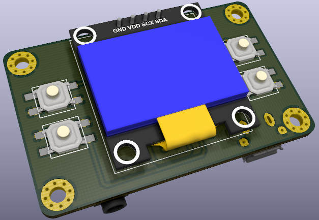
3D Model of display side of the board
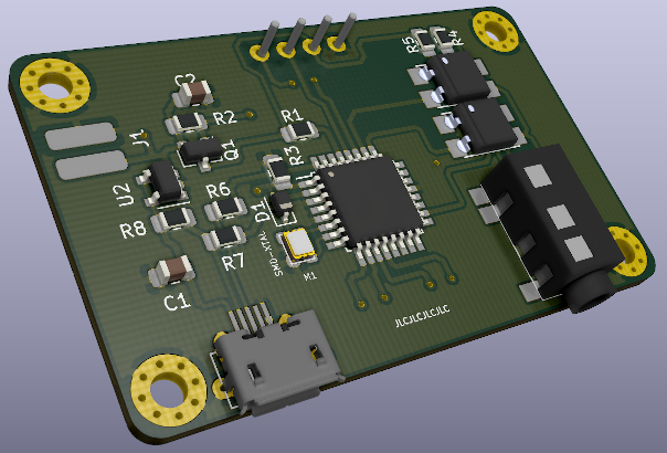
3D Model of component side of the board
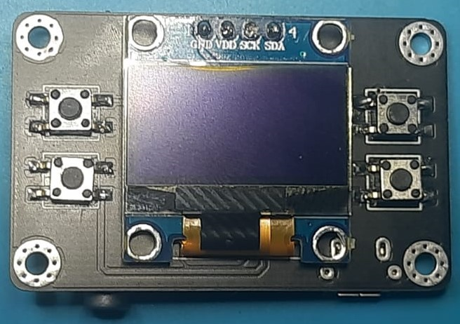
Display side of the board
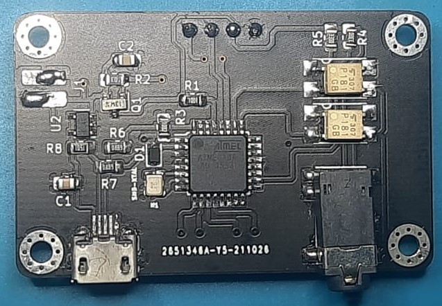
Component side of the board
Full documentation can be found here
PCB is designed using

Download KiCad project files here
Schematic can be found here
email: elechi@gmail.com
| Qty | Value | Footprint | References |
|---|---|---|---|
| 4 | MountingHole_Pad | MountingHole:MountingHole_2.5mm_Pad_Via | H1, H2, H3, H4 |
| 3 | 10k | Resistor_SMD:R_0805_2012Metric_Pad1.15x1.40mm_HandSolder | R2, R3, R4 |
| 2 | 1uF | Capacitor_SMD:C_0805_2012Metric_Pad1.15x1.40mm_HandSolder | C1, C2 |
| 2 | 470 | Resistor_SMD:R_0805_2012Metric_Pad1.15x1.40mm_HandSolder | R5, R6 |
| 2 | 68 | Resistor_SMD:R_0805_2012Metric_Pad1.15x1.40mm_HandSolder | R8, R9 |
| 2 | PC817SMD | timelapse:SMD4 | OK1, OK2 |
| 1 | 1.5k | Resistor_SMD:R_0805_2012Metric_Pad1.15x1.40mm_HandSolder | R10 |
| 1 | 12MHz | timelapse:SMDXTAL | M1 |
| 1 | 1N4148WS | Diode_SMD:D_SOD-323 | D1 |
| 1 | 1k | Resistor_SMD:R_0805_2012Metric_Pad1.15x1.40mm_HandSolder | R1 |
| 1 | 2N7002 | Package_TO_SOT_SMD:SOT-23 | Q1 |
| 1 | ATmega8-16AU | Package_QFP:TQFP-32_7x7mm_P0.8mm | U1 |
| 1 | Battery | Connector_PinHeader_2.54mm:PinHeader_1x02_P2.54mm_Vertical | J1 |
| 1 | CAMERA | timelapse:CAM-CONN-NOKIA | M2 |
| 1 | DWN | timelapse:4PIN-S | SW4 |
| 1 | MCP73811T | Package_TO_SOT_SMD:SOT-23-5 | U2 |
| 1 | NDS356 | Package_TO_SOT_SMD:SOT-23 | Q2 |
| 1 | OLED-CONN | timelapse:OLED-Display-0.96 | J2 |
| 1 | PROG | timelapse:4PIN-S | SW2 |
| 1 | PWR | timelapse:4PIN-S | SW1 |
| 1 | UP | timelapse:4PIN-S | SW3 |
| 1 | USB | timelapse:MICROUSB-V8 | J3 |
It measures 49 × 31 mm and has 2 copper layers, 1.4 mm thick.
31 parts, built around the ATMEGA8-16AU, 1N4148WS and NDS356P. The full list of its parts is on this page, with links to each part's symbol and footprint where PCBKit's library has them.
From the velechit/timelapse repository on GitHub, at the commit this page was made from: the board is board/documentation/boards/timelapse.kicad_pcb. PCBKit opens the board in the browser, with nothing to install.
Its repository states no licence, so its author keeps all rights: ask velechit before reusing the design.
NikodemBartnik/Small-Projects
All of smaller projects (Arduino, PCBs, electronics, code)


baldengineer/C64_1351_to_PS2_Mouse_PCB
PCB Design based on the [M]ouse project


SshgurkiratSingh/CCMS_PORTAL
A full-stack smart streetlight fleet management system with real-time monitoring, remote control, and analytics.

