4 layers96 × 70 mm

 Vakon84/isa8_eth
If EEPROM has not been programmed prior to assembly, now it is a good time to do so. The U3 EEPROM contains the following configuration for the RTL8019AS chip: MAC address ISA resources for jumperless configuration Base…
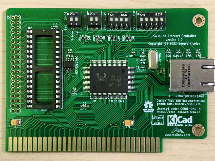
ISA8 Ethernet is an open-source printed circuit board by Vakon84, from the Vakon84/isa8_eth repository on GitHub, published under the CERN-OHL-S-2.0 licence. It is a 2-layer board of 104.1 × 74.9 mm with 34 parts on 134 nets, routed with 1,219 tracks and 95 vias.
It is built around the RTL8019AS-LF, 93LC46C-I/P and RJMG1BD3B8K1ANR. Its parts include 10 capacitors, 5 resistors, 4 switches, 3 ICs and 2 connectors. It belongs with the interfaces and adapters boards of this library.


ISA 8-Bit Ethernet Network Interface Controller
ISA 8-Bit Ethernet Controller is an open source network interface controller (NIC) card, designed specifically to be used in computers with 8-bit only ISA (aka XT) bus, such as IBM* PC, IBM* PC XT, various PC/XT compatibles, for example Micro 8088 system. It is based on Realtek RTL8019 ethernet controller and is NE2000-compatible.
If EEPROM has not been programmed prior to assembly, now it is a good time to do so. The U3 EEPROM contains the following configuration for the RTL8019AS chip:
This information can be programmed using PG8019 utility. The 8019AS.CFG file contains the recommended configuration. Make sure to edit it, and update the MAC address and the serial number. Note that the MAC address is given in the Big-endian format (that is the last byte has the least significant value), while the serial number is given in Little-endian format (that is the first byte has the least significant value).
A few notes about using PG8019:
Openmoko Inc. has generously allocated 00-1F-11-02-60-00 - 00-1F-11-02-7F-FF MAC addresses range for ISA 8-Bit Ethernet controller project. You can use MAC addresses from this range for your build, as long as you are using this design. Please apply for a different range if you're redesigning the board or re-using this Ethernet controller design in your own project. I ask you not to use 00-1F-11-02-60-00 - 00-1F-11-02-63-FF range (first 1024 addresses). I am using this range for the cards that I build.
This switch block sets the configuration mode
| Configuration Mode | Switch Position |
|---|---|
| Jumperless / RSET8019 | SW1.1 = OFF, SW1.2 = OFF |
| Switches | SW1.1 = ON, SW1.2 = OFF |
| PnP | SW1.1 = OFF, SW1.2 = ON |
This switch block, when the card is in the Switches configuration mode, sets the Ethernet controller IRQ
| IRQ | Switch Position |
|---|---|
| IRQ2 (on PC/XT) or IRQ9 (on AT) | SW2.1 = OFF, SW2.2 = OFF |
| IRQ3 | SW2.1 = ON, SW2.2 = OFF |
| IRQ4 | SW2.1 = OFF, SW2.2 = ON |
| IRQ5 | SW2.1 = ON, SW2.2 = ON |
This switch block, when the card is in the Switches configuration mode, sets the Ethernet controller I/O address
| I/O Address | SW3.1 | SW3.2 | SW3.3 | SW3.4 |
|---|---|---|---|---|
| 0x200 | OFF | OFF | ON | OFF |
| 0x220 | ON | OFF | ON | OFF |
| 0x240 | OFF | ON | ON | OFF |
| 0x260 | ON | ON | ON | OFF |
| 0x280 | OFF | OFF | ON | ON |
| 0x2A0 | ON | OFF | ON | ON |
| 0x2C0 | OFF | ON | ON | ON |
| 0x2E0 | ON | ON | ON | ON |
| 0x300 | OFF | OFF | OFF | OFF |
| 0x320 | ON | OFF | OFF | OFF |
| 0x340 | OFF | ON | OFF | OFF |
| 0x360 | ON | ON | OFF | OFF |
| 0x380 | OFF | OFF | OFF | ON |
| 0x3A0 | ON | OFF | OFF | ON |
| 0x3C0 | OFF | ON | OFF | ON |
| 0x3E0 | ON | ON | OFF | ON |
This switch block, when the card is in the Switches configuration mode, sets the Ethernet controller boot ROM address and size
| ROM Address | ROM Size | SW4.1 | SW4.2 | SW4.3 | SW4.4 | SW4.5 |
|---|---|---|---|---|---|---|
| ROM Disabled | Not applicable | * | * | * | OFF | OFF |
| 0xC0000 | 16 KiB | OFF | OFF | OFF | OFF | ON |
| 0xC4000 | 16 KiB | ON | OFF | OFF | OFF | ON |
| 0xC8000 | 16 KiB | OFF | ON | OFF | OFF | ON |
| 0xCC000 | 16 KiB | ON | ON | OFF | OFF | ON |
| 0xD0000 | 16 KiB | OFF | OFF | ON | OFF | ON |
| 0xD4000 | 16 KiB | ON | OFF | ON | OFF | ON |
| 0xD8000 | 16 KiB | OFF | ON | ON | OFF | ON |
| 0xDC000 | 16 KiB | ON | ON | ON | OFF | ON |
| 0xC0000 | 32 KiB | OFF | OFF | OFF | ON | OFF |
| 0xC8000 | 32 KiB | ON | OFF | OFF | ON | OFF |
| 0xD0000 | 32 KiB | OFF | ON | OFF | ON | OFF |
| 0xD8000 | 32 KiB | ON | ON | OFF | ON | OFF |
| 0xC0000 | 64 KiB | OFF | OFF | ON | ON | OFF |
| 0xD0000 | 64 KiB | ON | OFF | ON | ON | OFF |
| 0xC0000 | 16 KiB / Page mode | OFF | OFF | OFF | ON | ON |
| 0xC4000 | 16 KiB / Page mode | ON | OFF | OFF | ON | ON |
| 0xC8000 | 16 KiB / Page mode | OFF | ON | OFF | ON | ON |
| 0xCC000 | 16 KiB / Page mode | ON | ON | OFF | ON | ON |
| 0xD0000 | 16 KiB / Page mode | OFF | OFF | ON | ON | ON |
| 0xD4000 | 16 KiB / Page mode | ON | OFF | ON | ON | ON |
| 0xD8000 | 16 KiB / Page mode | OFF | ON | ON | ON | ON |
| 0xDC000 | 16 KiB / Page mode | ON | ON | ON | ON | ON |
This connector can be used to add up to 4 MiB of optional memory (ROM or RAM). The memory, if larger than 64 KiB, can be accessed using the page mode.
| Pin | Description | Pin | Description |
|---|---|---|---|
| 1 | 5V | 2 | 5V |
| 3 | No connection | 4 | A21 |
| 5 | No connection | 6 | A20 |
| 7 | No connection | 8 | A19 |
| 9 | A18 | 10 | /MEMW |
| 11 | A16 | 12 | A17 |
| 13 | A15 | 14 | A14 |
| 15 | A12 | 16 | A13 |
| 17 | A7 | 18 | A8 |
| 19 | A6 | 20 | A9 |
| 21 | A5 | 22 | A11 |
| 23 | A4 | 24 | /MEMR |
| 25 | A3 | 26 | A10 |
| 27 | A2 | 28 | /CS |
| 29 | A1 | 30 | D7 |
| 31 | A0 | 32 | D6 |
| 33 | D0 | 34 | D5 |
| 35 | D1 | 36 | D4 |
| 37 | D2 | 38 | D3 |
| 39 | GND | 40 | GND |
ISA 8-bit Ethernet project on Mouser.com - View and order all components except of the PCB and the Realtek RTL8019 IC.
ISA 8-bit Ethernet project on OSH Park - View and order the PCB.
| Component type | Reference | Description | Quantity | Possible sources and notes |
|---|---|---|---|---|
| PCB | ISA 8-bit Ethernet PCB - Version 1.0 | 1 | Buy from my Tindie store: ISA 8-bit Ethernet PCB, and optionally a preprogrammed EEPROM, or order from a PCB manufacturer of your choice using provided Gerber or KiCad files | |
| Integrated Circuit | U1 | Realtek RTL8019AS Ethernet Controller | 1 | Authorized Realtek distributors or eBay |
| Integrated Circuit | U2 | SST39SF040 - 512 KiB Flash ROM, 32 pin DIP | 1 | Optional - Boot ROM. Mouser 804-39SF0407CPHE |
| Integrated Circuit | U3 | 93C46 - 1 Kbit EEPROM, 4 pin SOIC | 1 | Mouser 511-M93C46-WMN6TP |
| Quartz Crystal | Y1 | 20 MHz, 18pF, HC-49U | 1 | Mouser 774-ATS200C |
| Ethernet Jack | J1 | Amphenol RJMG1BD3B8K1ANR - Ethernet jack with magnetics | 1 | Mouser 523-RJMG1BD3B8K1ANR |
| DIP Switch | SW1, SW2 | DIP switch, 2 position, SPST | 2 | Mouser 774-2102MS |
| DIP Switch | SW3 | DIP switch, 4 position, SPST | 1 | Mouser 774-2104MS |
| DIP Switch | SW4 | DIP switch, 5 position, SPST | 1 | Mouser 774-2105MS |
| Capacitor | C1, C2 | 10pF MLCC Capacitor, 0603 SMT | 2 | Mouser 77-VJ0603A100JXACBC |
| Capacitor | C3, C4 | 0.01uF MLCC Capacitor, 0603 SMT | 2 | Mouser 77-VJ0603Y103JXACBC |
| Capacitor | C5 - C8 | 0.1uF MLCC Capacitor, 0603 SMT | 4 | Mouser 77-VJ0603Y104JXJPBC |
| Capacitor | C1, C2 | 22uF Tantalum Capacitor, 1210 SMT | 2 | Mouser 581-TAJB226K016TNJ |
| Resistor | R1 | 200 Ohm Resistor, 0603 SMT | 1 | Mouser 603-RC0603FR-13200RL |
| Resistor | R2, R3 | 470 Ohm Resistor, 0603 SMT | 2 | Mouser 603-RC0603FR-13470RL |
| Resistor | R6 | 27 kOhm Resistor, 0603 SMT | 1 | Mouser 603-RC0603FR-1327KL |
| Resistor | R7 | 1 MOhm Resistor, 0603 SMT | 1 | Mouser 603-RC0603FR-131ML |
| Resistor Array | RN1 - RN4 | 10 kOhm x 4 Resistor Array, 0603 SMT | 4 | Mouser 667-EXB-38V103JV |
| IC Socket | U2 | 32 pin DIP | 1 | Mouser 517-4832-6000-CP |
The Realtek RTL8019AS uses 93C46 - 1Kbit / 128 bytes EEPROM to store the configuration. The EEPROM is accessed using 16-bit word mode, with data being stored in Big-endian format. This means that the bytes should be swapped when the EEPROM content is accessed on an x86 system.
| Address | Size | Content | Default Configuration for ISA 8-Bit Ethernet |
|---|---|---|---|
| 0x00 - 0x03 | 4 | CONFIG1, CONFIG2, CONFIG3, CONFIG4 | |
| 0x00 | 1 | CONFIG1 | 0x07 |
| 0x01 | 1 | CONFIG2 | 0x00 |
| 0x02 | 1 | CONFIG3 | 0xD0 |
| 0x03 | 1 | CONFIG4 | 0x01 |
| 0x04 - 0x09 | 6 | Ethernet ID (MAC Address) | 0x00 0x1F 0x11 0x02 0x70 0x00 |
| 0x0A - 0x11 | 8 | Product ID | 0x49 0x53 0x41 0x38 0x45 0x54 0x48 0x20 |
| 0x12 - 0x1A | 9 | PnP header | |
| 0x12 - 0x15 | 4 | Vendor ID (0-3) | |
| 0x12 - 0x13 | 2 | Vendor ID - compressed ASCII (00000=A) | 0x4A 0x8C - 0 10010=R 10100=T 01100=L |
| 0x14 - 0x15 | 2 | Vendor ID - product number | 0x80 0x19 - 8019 |
| 0x16 - 0x19 | 4 | Serial Number (0-3) | 0x00 0x10 0x00 0x00 |
| 0x1A | 1 | Checksum | ? |
| 0x1B - 0x7F | 101 | PnP Resource Data | |
| 0x1B - 0x1D | 3 | PnP Version Number | |
| 0x1B | 1 | Item byte | 0x0A |
| 0x1C | 1 | PnP Version | 0x10 |
| 0x1D | 1 | Vendor Version | 0x10 |
| 0x1E - 0x3B | 37 | ANSI Identifier String | |
| 0x1E | 1 | Item byte | 0x82 |
| 0x1F | 1 | Length, bits 7-0 | 0x24 |
| 0x20 | 1 | Length, bits 15-8 | 0x00 |
| 0x21 - 0x44 | 36 | Identifier String | "ISA 8-Bit Plug & Play Ethernet Card", 0x00 |
| 0x45 - 0x4B | 7 | Logical Device ID | |
| 0x45 | 1 | Item byte | 0x16 |
| 0x46 - 0x49 | 4 | Logical Device ID 0-3 | 0x00 0x00 0x80 0x19 |
| 0x4A | 1 | Flag 0 | 0x02 (Boot ROM disabled) or 0x03 (Boot ROM enabled) |
| 0x4B | 1 | Flag 1 | 0x00 |
| 0x4C - 0x50 | 5 | Compatible Device ID (NE2000 compatible) | |
| 0x4C | 1 | Item byte | 0x1C |
| 0x4D - 0x50 | 4 | Compatible ID | 0x41 0xD0 0x80 0xD6 |
| 0x51 - 0x58 | 8 | I/O Format | |
| 0x51 | 1 | Item byte | 0x47 |
| 0x52 | 1 | I/O Information | 0x00 |
| 0x53 | 1 | Minimal I/O base, bits 7-0 | 0x20 |
| 0x54 | 1 | Minimal I/O base, bits 15-8 | 0x02 |
| 0x55 | 1 | Maximal I/O base, bits 7-0 | 0x80 |
| 0x56 | 1 | Maximal I/O base, bits 15-8 | 0x03 |
| 0x57 | 1 | Base alignment | 0x20 |
| 0x58 | 1 | Range length | 0x20 |
| 0x59 - 0x5C | 4 | IRQ Format | |
| 0x59 | 1 | Item byte | 0x23 - Small item name = 0x04 (IRQ), Length = 3 |
| 0x5A | 1 | IRQ mask bits 7-0 | 0x3C - IRQ 0-7 mask - IRQ5, IRQ4, IRQ3, IRQ2 |
| 0x5B | 1 | IRQ mask bits 15-8 | 0x02 - IRQ 8-15 mask - IRQ9 (note: IRQ9 is the same as IRQ2, others are not available on an 8-bit slot) |
| 0x5C | 1 | IRQ information | 0x01 - High true edge sensitive |
| 0x5D - 0x6A | 12 | Memory Format (optional) | 64 KiB Boot ROM (16 KiB Boot ROM) |
| 0x5D | 1 | Item byte | 0x81 |
| 0x5E | 1 | Length, bits 7-0 | 0x09 |
| 0x5F | 1 | Length, bits 15-8 | 0x00 |
| 0x60 | 1 | Memory information | 0x40 |
| 0x61 | 1 | Minimal base, bits 15-8 | 0x00 |
| 0x62 | 1 | Minimal base, bits 24-16 | 0x0C |
| 0x63 | 1 | Maximal base, bits 7-0 | 0x00 (0xC0 for 16 KiB) |
| 0x64 | 1 | Maximal base, bits 15-8 | 0x0D |
| 0x65 | 1 | Base alignment, bits 7-0 | 0x00 |
| 0x66 | 1 | Base alignment, bits 15-8 | 0x00 (0x40 for 16 KiB) |
| 0x67 | 1 | Range length bits 15-8 | 0x00 (0x40 for 16 KiB) |
| 0x68 | 1 | Range length bits 24-16 | 0x01 (0x00 for 16 KiB) |
| 0x69 - 0x6A | 2 | End Tag | |
| 0x6B | 1 | Item byte | 0x79 |
| 0x6C | 1 | Checksum of the resource data | 0x1F |
| 0x6D-0x7F | ? | Unused space | 0xFF |
ISA 8-bit Ethernet is an open source hardware project certified by Open Source Hardware Association, certification UID is US002001. The hardware design itself, including schematic and PCB layout design files are licensed under the strongly-reciprocal variant of CERN Open Hardware Licence version 2. The NE2000 driver code is licensed under GNU General Public License v2. Documentation, including this file, is licensed under the Creative Commons Attribution-ShareAlike 4.0 International License.
KiCad symbols and modules used in this project are available in my KiCad library repository
| Qty | Value | Footprint | References |
|---|---|---|---|
| 4 | 0.1uF | Capacitor_SMD:C_0603_1608Metric_Pad1.08x0.95mm_HandSolder | C5, C6, C7, C8 |
| 4 | 10k | Resistor_SMD:R_Array_Convex_4x0603 | RN1, RN2, RN3, RN4 |
| 2 | 0.01uF | Capacitor_SMD:C_0603_1608Metric_Pad1.08x0.95mm_HandSolder | C3, C4 |
| 2 | 10pF | Capacitor_SMD:C_0603_1608Metric_Pad1.08x0.95mm_HandSolder | C1, C2 |
| 2 | 22uF | Capacitor_Tantalum_SMD:CP_EIA-3528-15_AVX-H_Pad1.50x2.35mm_HandSolder | C9, C10 |
| 2 | 470 | Resistor_SMD:R_0603_1608Metric_Pad0.98x0.95mm_HandSolder | R2, R3 |
| 2 | M3 | MountingHole:MountingHole_3.2mm_M3_Pad_Via | HOLE1, HOLE2 |
| 1 | 1M | Resistor_SMD:R_0603_1608Metric_Pad0.98x0.95mm_HandSolder | R7 |
| 1 | 200 | Resistor_SMD:R_0603_1608Metric_Pad0.98x0.95mm_HandSolder | R1 |
| 1 | 20MHz | My_Components:Crystal_HC-49U_Vert | Y1 |
| 1 | 27k | Resistor_SMD:R_0603_1608Metric_Pad0.98x0.95mm_HandSolder | R6 |
| 1 | 93LC46C | Package_SO:SO-8_3.9x4.9mm_P1.27mm | U3 |
| 1 | BUSPC_DEV | My_Components:Conn_Edge_PCB_ISA8 | BUS1 |
| 1 | CONFIG | My_Components:Switch_DIP_2_Positions | SW1 |
| 1 | IO_ADDR | My_Components:Switch_DIP_4_Positions | SW3 |
| 1 | IRQ | My_Components:Switch_DIP_2_Positions | SW2 |
| 1 | MEM_EXT | My_Components:Conn_Pin_Header_20x2_2.54mm | J2 |
| 1 | RJMG1BD3B8K1ANR | Connector_RJ:RJ45_Amphenol_RJMG1BD3B8K1ANR | J1 |
| 1 | ROM_ADDR | My_Components:Switch_DIP_5_Positions | SW4 |
| 1 | RTL8019AS | My_Components:IC_PQFP-100_14x20mm_P0.65mm_Hand_Soldering | U1 |
| 1 | SST39SF040 | My_Components:Socket_DIP32_600 | U2 |
The 32 most common of 34 parts.
It measures 104.1 × 74.9 mm and has 2 copper layers, 1.6 mm thick.
34 parts, built around the RTL8019AS-LF, 93LC46C-I/P and RJMG1BD3B8K1ANR. The full list of its parts is on this page, with links to each part's symbol and footprint where PCBKit's library has them.
From the Vakon84/isa8_eth repository on GitHub, at the commit this page was made from: the board is KiCad/ISA8_Ethernet.kicad_pcb. PCBKit opens the board in the browser, with nothing to install.
Its repository publishes it under the CERN-OHL-S-2.0 licence: you may reuse it on that licence's terms (keep the author's notice, and for a copyleft licence share your changes alike).


Neotron-Compute/Neotron-Common-Hardware
Contains KiCad footprints and symbols shared across multiple Neotron projects.

Johannes4Linux/Ethernet_PCBs
PCBs for my GNU/Linux & Ethernet Tutorials


Maverick-Shark/X65_BigMiST
The X65 is an ultimate computer for everyone interested in the venerable 65-series of 8-bit and 16-bit CPUs, i.e. the 6502 and 65816.
