2 layers35 × 50 mm
 vadymtaranenko/Boat-Controller
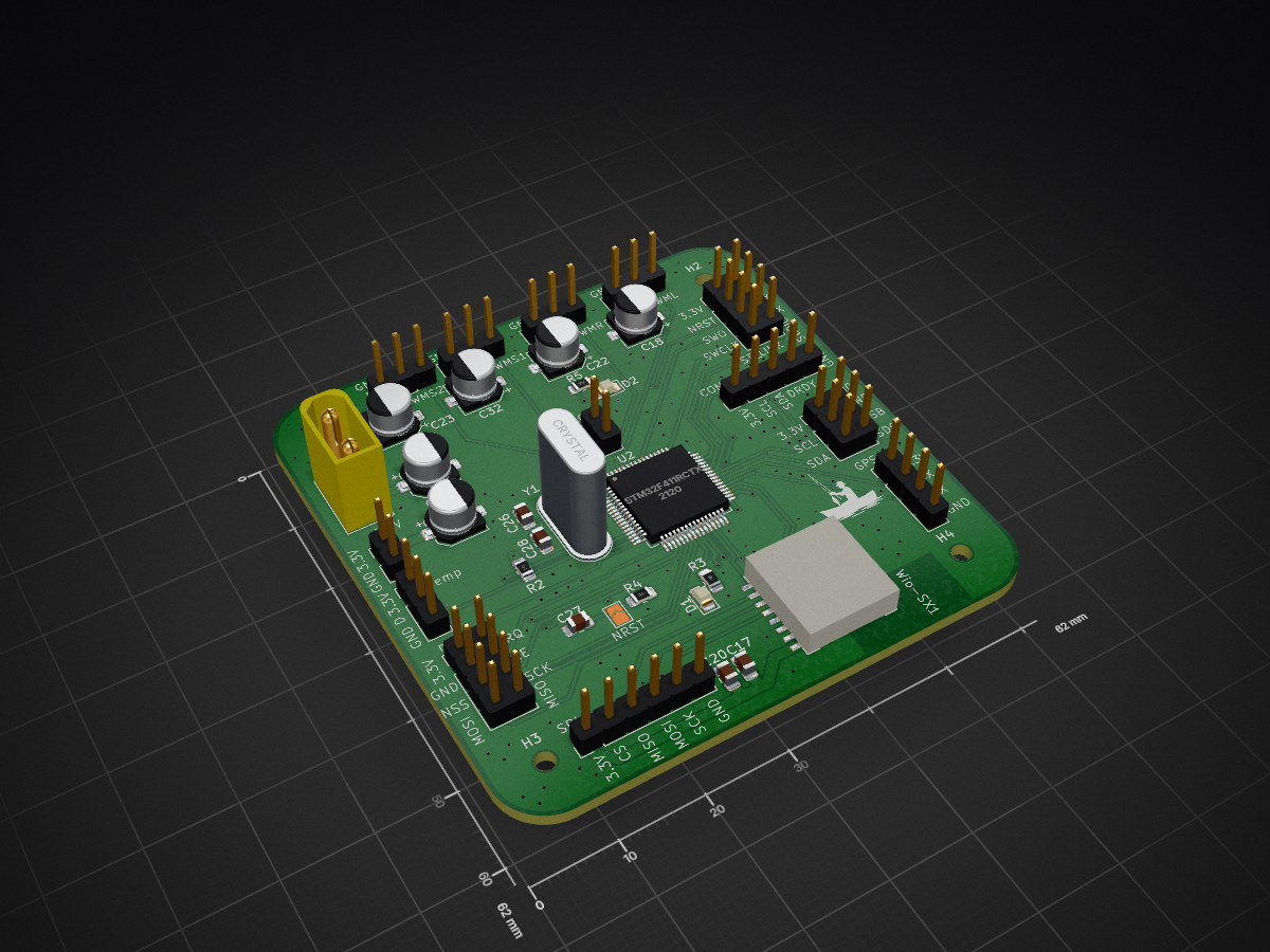
Płyta główna (odbiornik) łodzi zanętowej. Układ odpowiada za integrację systemów nawigacji, telemetrii środowiskowej, dwukierunkowej komunikacji radiowej oraz sprzętowego sterowania napędem.
Boat Controller is an open-source printed circuit board by vadymtaranenko, from the vadymtaranenko/Boat-Controller repository on GitHub. It is a 2-layer board of 62 × 62 mm with 60 parts on 59 nets, routed with 411 tracks and 155 vias.
Its parts include 29 capacitors, 13 connectors, 5 resistors, 2 ICs and 2 diodes. It belongs with the STM32 boards of this library.
Płyta główna (odbiornik) łodzi zanętowej. Układ odpowiada za integrację systemów nawigacji, telemetrii środowiskowej, dwukierunkowej komunikacji radiowej oraz sprzętowego sterowania napędem. Projekt wykonany w środowisku KiCad (2-Layer PCB).
/Hardware - Pliki źródłowe środowiska KiCad (schemat, obwód drukowany, zintegrowane biblioteki lokalne)./Docs - Schemat ideowy wyeksportowany do formatu PDF oraz rendery 3D płytki.| Qty | Value | Footprint | References |
|---|---|---|---|
| 15 | 100n | Capacitor_SMD:C_0805_2012Metric_Pad1.18x1.45mm_HandSolder | C5, C6, C7, C8, C9, C11, C17, C19, C20, C21, C24, C25, C27, C30, C31 |
| 5 | Conn_01x03_Pin | Connector_PinHeader_2.54mm:PinHeader_1x03_P2.54mm_Vertical | J2, J6, J7, J9, J10 |
| 4 | 470u | Capacitor_SMD:CP_Elec_5x4.5 | C18, C22, C23, C32 |
| 4 | MountingHole | MountingHole:MountingHole_2.2mm_M2_ISO7380 | H1, H2, H3, H4 |
| 2 | 100n | Capacitor_SMD:C_0805_2012Metric | C2, C3 |
| 2 | 10k | Resistor_SMD:R_0805_2012Metric_Pad1.20x1.40mm_HandSolder | R1, R4 |
| 2 | 10u | Capacitor_SMD:CP_Elec_5x4.5 | C35, C36 |
| 2 | 1k | Resistor_SMD:R_0805_2012Metric_Pad1.20x1.40mm_HandSolder | R3, R5 |
| 2 | 27p | Capacitor_SMD:C_0805_2012Metric_Pad1.18x1.45mm_HandSolder | C26, C28 |
| 2 | 4.7u | Capacitor_SMD:CP_Elec_5x4.5 | C33, C34 |
| 2 | Conn_02x04_Counter_Clockwise | Connector_PinHeader_2.54mm:PinHeader_2x04_P2.54mm_Vertical | J4, J13 |
| 2 | RED | LED_SMD:LED_0805_2012Metric_Pad1.15x1.40mm_HandSolder | D1, D2 |
| 1 | 4.7u | Capacitor_SMD:C_0805_2012Metric_Pad1.18x1.45mm_HandSolder | C29 |
| 1 | 4.7u | Capacitor_SMD:C_0805_2012Metric | C1 |
| 1 | 4k7 | Resistor_SMD:R_0805_2012Metric_Pad1.20x1.40mm_HandSolder | R2 |
| 1 | Conn_01x02_Pin | Connector_PinHeader_2.54mm:PinHeader_1x02_P2.54mm_Vertical | J1 |
| 1 | Conn_01x02_Pin | Connector_AMASS:AMASS_XT30U-F_1x02_P5.0mm_Vertical | J8 |
| 1 | Conn_01x04_Pin | Connector_PinHeader_2.54mm:PinHeader_1x04_P2.54mm_Vertical | J11 |
| 1 | Conn_01x05_Pin | Connector_PinHeader_2.54mm:PinHeader_1x05_P2.54mm_Vertical | J5 |
| 1 | Conn_01x06_Pin | Connector_PinHeader_2.54mm:PinHeader_1x06_P2.54mm_Vertical | J14 |
| 1 | Conn_02x03_Counter_Clockwise | Connector_PinHeader_2.54mm:PinHeader_2x03_P2.54mm_Vertical | J3 |
| 1 | Crystal | Crystal:Crystal_HC49-U_Vertical | Y1 |
| 1 | Jumper_2_Open | Connector_PinHeader_2.54mm:PinHeader_1x02_P2.54mm_Vertical | JP1 |
| 1 | LD1086D2M33TR | Package_TO_SOT_SMD:TO-263-3_TabPin2 | U1 |
| 1 | LOGO | LOGO | G*** |
| 1 | STM32F411RCTx | Package_QFP:LQFP-64_10x10mm_P0.5mm | U2 |
| 1 | SolderJumper_2_Open | Jumper:SolderJumper-2_P1.3mm_Open_TrianglePad1.0x1.5mm | JP2 |
| 1 | U2 | LIBS:LoRA_Wio-SX1 | Wio-SX1 |
It measures 62 × 62 mm and has 2 copper layers, 1.58 mm thick.
60 parts. The full list of its parts is on this page, with links to each part's symbol and footprint where PCBKit's library has them.
From the vadymtaranenko/Boat-Controller repository on GitHub, at the commit this page was made from: the board is Hardware/Boat_ controller.kicad_pcb and its schematic Hardware/Boat_ controller.kicad_sch. PCBKit opens the board in the browser, with nothing to install.
Its repository states no licence, so its author keeps all rights: ask vadymtaranenko before reusing the design.


sd2psx/pcb
The PCB must be produced in 0.8mm thickness. Production files are provided under the "Releases" tab. These do not include the through-hole OLED module.


BitDogLab/BitDogLab
Open-source educational hardware for embedded systems, programming, electronics, and physical computing.