


4 layers74 × 104 mm

NorthernStudios FPGA Dev Board
NS FPGA is an open-source printed circuit board by uzzambutt, from the uzzambutt/NorthernStudios-FPGA-Dev-Board repository on GitHub, published under the MIT licence. It is a 6-layer board of 27.2 × 64.8 mm with 47 parts on 93 nets, routed with 599 tracks and 86 vias.
It is built around the AP2112K-3.3 and BSS138. Its parts include 17 capacitors, 12 resistors, 4 ICs, 4 connectors and 2 diodes. It belongs with the fPGA and programmable logic and microcontroller boards boards and the FPGA and CPLD boards of this library.



Designed by Muhammad Uzzam Butt // Made for Macondo
This FPGA Devboard is designed in KiCad v9.0 and is built around the Gowin GW1NSR-4C, a hybrid FPGA chip containing an embedded ARM Cortex-M3 microcontroller.
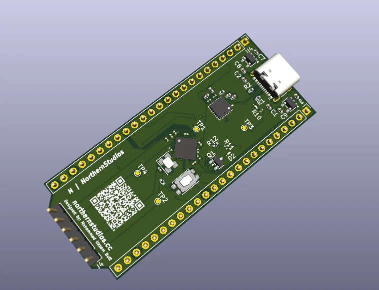
A complete list of components required to assemble the dev board is detailed in the table below (sourced from bom.csv [blocked]):
| Comment | Designator | Footprint | LCSC | Quantity |
|---|---|---|---|---|
| 0.1uF | C1, C4, C6 | C_0402_1005Metric | C141382 | 3 |
| 0.1uF | C11, C12, C13, C14, C15, C16, C17 | C_0201_0603Metric | C66938 | 7 |
| 10k | R12, R3, R9 | R_0402_1005Metric | C25725 | 3 |
| 10uF | C10, C7, C8, C9 | C_0402_1005Metric | C15525 | 4 |
| 1k | R10 | R_0201_0603Metric | C131396 | 1 |
| 22.1k | R4 | R_0201_0603Metric | C423662 | 1 |
| 330 | R11 | R_0201_0603Metric | C274872 | 1 |
| 4.7k | R7, R8 | R_0201_0603Metric | C142008 | 2 |
| 4.7uF | C2, C3, C5 | C_0402_1005Metric | C23733 | 3 |
| 47.5k | R5 | R_0201_0603Metric | C166179 | 1 |
| 5.1k | R1, R2 | R_0402_1005Metric | C25905 | 2 |
| AP2112K-1.2 | U4 | SOT-23-5 | C49451994 | 1 |
| AP2112K-3.3 | U3 | SOT-23-5 | C3021085 | 1 |
| BSS138 | Q1 | SOT-23 | C52895 | 1 |
| CP2102N-Axx-xQFN24 | U2 | QFN-24-1EP_4x4mm_P0.5mm_EP2.6x2.6mm | C969151 | 1 |
| LED | D1, D2 | LED_0201_0603Metric | C3646922 | 2 |
| R22 | R6 | R_0201_0603Metric | C142011 | 1 |
| SG-8002CE(24.0000M) | Y1 | Oscillator_SMD_SeikoEpson_SG8002CE-4Pin_3.2x2.5mm | C390322 | 1 |
| SW_Push | SW1 | SW_SPST_EVQP2_ShortPushTravel_H2.1mm | C2915174 | 1 |
| USB_C_Receptacle_USB2.0_14P | J1 | USB_C_Receptacle_HCTL_HC-TYPE-C-16P-01A | C165948 | 1 |
| GW1NSR-4C-MG64P | U1 | BGA-64_8x8_4.2x4.2mm | Gowin GW1NSR-4C-MG64P | 1 |
| TestPoint | TP4 | TestPoint_Pad_D1.0mm | 1 | |
| TestPoint | TP3 | TestPoint_Pad_D1.0mm | 1 | |
| TestPoint | TP2 | TestPoint_Pad_D1.0mm | 1 | |
| TestPoint | TP1 | TestPoint_Pad_D1.0mm | 1 | |
| Jtag PIN | J4 | PinHeader_1x06_P2.54mm_Vertical | 1 | |
| Conn_01x24_Pin | J3 | PinHeader_1x24_P2.54mm_Vertical | 1 | |
| Conn_01x24_Pin | J2 | PinHeader_1x24_P2.54mm_Vertical | 1 |
This project is open-source hardware licensed under the MIT License.
Designed by Muhammad Uzzam Butt // Made for Macondo
| Qty | Value | Footprint | References |
|---|---|---|---|
| 7 | 0.1uF | Capacitor_SMD:C_0201_0603Metric | C11, C12, C13, C14, C15, C16, C17 |
| 4 | 10uF | Capacitor_SMD:C_0402_1005Metric | C7, C8, C9, C10 |
| 4 | TestPoint | TestPoint:TestPoint_Pad_D1.0mm | TP1, TP2, TP3, TP4 |
| 3 | 0.1uF | Capacitor_SMD:C_0402_1005Metric | C1, C4, C6 |
| 3 | 10k | Resistor_SMD:R_0402_1005Metric | R3, R9, R12 |
| 3 | 4.7uF | Capacitor_SMD:C_0402_1005Metric | C2, C3, C5 |
| 2 | 4.7k | Resistor_SMD:R_0201_0603Metric | R7, R8 |
| 2 | 5.1k | Resistor_SMD:R_0402_1005Metric | R1, R2 |
| 2 | Conn_01x24_Pin | Connector_PinHeader_2.54mm:PinHeader_1x24_P2.54mm_Vertical | J2, J3 |
| 2 | LED | LED_SMD:LED_0201_0603Metric | D1, D2 |
| 1 | 1k | Resistor_SMD:R_0201_0603Metric | R10 |
| 1 | 22.1k | Resistor_SMD:R_0201_0603Metric | R4 |
| 1 | 330 | Resistor_SMD:R_0201_0603Metric | R11 |
| 1 | 47.5k | Resistor_SMD:R_0201_0603Metric | R5 |
| 1 | AP2112K-1.2 | Package_TO_SOT_SMD:SOT-23-5 | U4 |
| 1 | AP2112K-3.3 | Package_TO_SOT_SMD:SOT-23-5 | U3 |
| 1 | BSS138 | Package_TO_SOT_SMD:SOT-23 | Q1 |
| 1 | CP2102N-Axx-xQFN24 | Package_DFN_QFN:QFN-24-1EP_4x4mm_P0.5mm_EP2.6x2.6mm | U2 |
| 1 | Jtag PIN | Connector_PinHeader_2.54mm:PinHeader_1x06_P2.54mm_Vertical | J4 |
| 1 | LOGO | LOGO | G*** |
| 1 | R22 | Resistor_SMD:R_0201_0603Metric | R6 |
| 1 | SG-8002CE(24.0000M) | Oscillator:Oscillator_SMD_SeikoEpson_SG8002CE-4Pin_3.2x2.5mm | Y1 |
| 1 | SW_Push | Button_Switch_SMD:SW_SPST_EVQP2_ShortPushTravel_H2.1mm | SW1 |
| 1 | USB_C_Receptacle_USB2.0_14P | Connector_USB:USB_C_Receptacle_HCTL_HC-TYPE-C-16P-01A | J1 |
| 1 | ~ | Gowin FPGA:BGA-64_8x8_4.2x4.2mm | U1 |


joshajohnson/Hub20
Hub20 is a numpad with a bunch of features you never knew you needed.

ianklug/bemini
A miniature mechanical keyboard controller with a rotary encoder for staggered-key rhythm games.

jnicolson/panasonic_ac_wifi
Module to interface with the CN-CNT port on Panasonic airconditioner units

It measures 27.2 × 64.8 mm and has 6 copper layers, 1.6 mm thick.
47 parts, built around the AP2112K-3.3 and BSS138. The full list of its parts is on this page, with links to each part's symbol and footprint where PCBKit's library has them.
From the uzzambutt/NorthernStudios-FPGA-Dev-Board repository on GitHub, at the commit this page was made from: the board is hardware/NS FPGA.kicad_pcb and its schematic hardware/NS FPGA.kicad_sch. PCBKit opens the board in the browser, with nothing to install.
Its repository publishes it under the MIT licence: you may reuse it on that licence's terms (keep the author's notice, and for a copyleft licence share your changes alike).