2 layers30 × 40.1 mm
SIPM02
mlab-modules/SIPM02
The module is electro-mechanical interface between scintillation crystal and signal processing unit.
39 parts
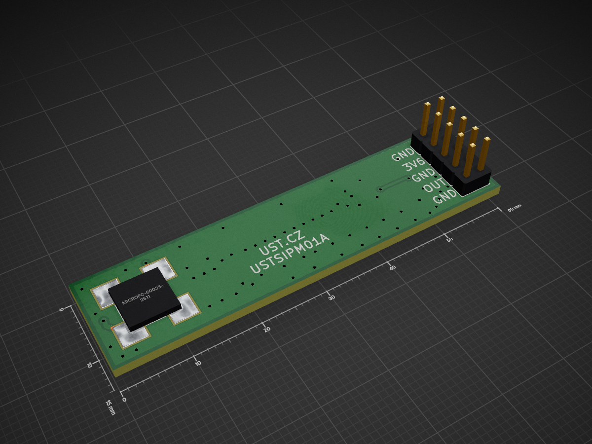
 ust-modules/USTSIPM012
Silicon photomultiplier interface module
USTSIPM01 is an open-source printed circuit board by ust-modules, from the ust-modules/USTSIPM01 repository on GitHub. It is a 2-layer board of 60 × 15 mm with 39 parts on 17 nets, routed with 111 tracks and 68 vias.
It is built around the OPA836IDBV and BZX585-B5V6,115-JSM. Its parts include 16 capacitors, 12 resistors, 5 connectors, 3 ICs and 2 diodes.


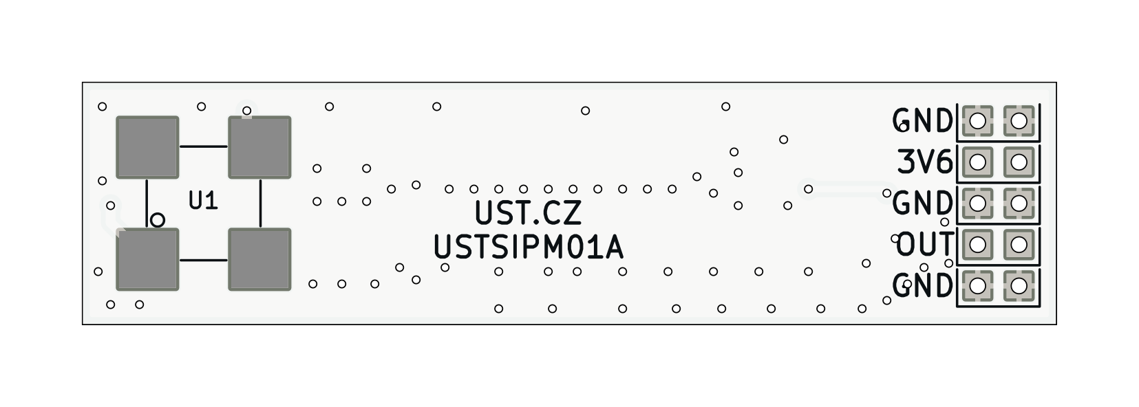
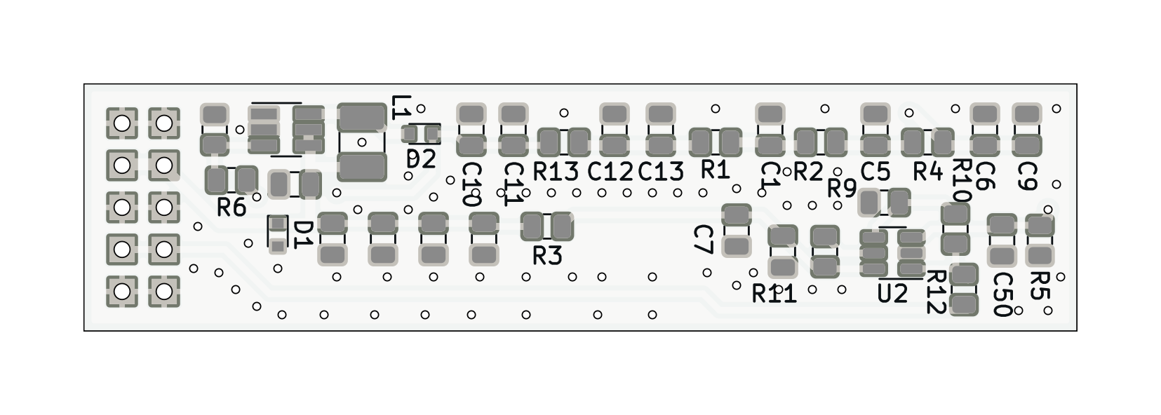
Complete analog front‑end for Silicon Photomultipliers (SiPM). The module provides resistor-configurable high‑voltage bias for the SiPM sensor and a low‑noise, wideband readout stage suitable for timing and amplitude measurements.
flowchart LR
    V["3V6"] -->|Bias supply| MAX5026["MAX5026 Boost"]
    MAX5026 -->|VBIAS 25-32 V| SiPM["SiPM MicroFC-60035"]
    SiPM -->|A| OPA836["OPA836 Readout"]
    OPA836 --> OUT["OUT"]
V33["+3.3 V"] --> OPA836Note (SiPM operating point): The sensor is biased at Vout = VBR + VOV, where VBR is the device’s breakdown voltage and VOV is the selected overvoltage. Typical recommended VOV = 1…5 V. Temperature coefficient of VBR ≈ +21.5 mV/°C (adjust bias accordingly).
The MAX5026 feedback follows:
Vout = 1.25 V × (1 + R2/R3)Default population (R2 = 3.9 MΩ, R3 = 160 kΩ) yields:
Vout ≈ 1.25 × (1 + 3.9M/160k) ≈ 31.7 VExample design for MicroFC‑60035 with typical VBR ≈ 24.7 V:
Keep the feedback resistors in the MΩ range to minimize divider current, and place them tight to the FB node. Use a low‑leakage layout around FB. Treat the SiPM and the module as ESD‑sensitive.
| Qty | Value | Footprint | References |
|---|---|---|---|
| 6 | 100nF | Capacitor_SMD:C_0805_2012Metric | C5, C6, C8, C11, C12, C50 |
| 6 | 10uF | Capacitor_SMD:C_0805_2012Metric | C2, C3, C4, C7, C14, C15 |
| 5 | HEADER_2x01_PARALLEL | Mlab_Pin_Headers:Straight_2x01 | J4, J5, J6, J8, J9 |
| 3 | 100R | Resistor_SMD:R_0805_2012Metric | R1, R3, R13 |
| 3 | 10R | Resistor_SMD:R_0805_2012Metric | R2, R4, R5 |
| 2 | 1uF/50V | Capacitor_SMD:C_0805_2012Metric | C10, C13 |
| 1 | 10k | Resistor_SMD:R_0805_2012Metric | R11 |
| 1 | 10nF | Capacitor_SMD:C_0805_2012Metric | C9 |
| 1 | 10uF/35V | Capacitor_SMD:C_0805_2012Metric | C1 |
| 1 | 12k | Resistor_SMD:R_0805_2012Metric | R10 |
| 1 | 160k | Resistor_SMD:R_0805_2012Metric | R7 |
| 1 | 1k | Resistor_SMD:R_0805_2012Metric | R12 |
| 1 | 3M9 | Resistor_SMD:R_0805_2012Metric | R6 |
| 1 | 400uH cca 0,9mA NLV10JT391 | Inductor_SMD:L_1210_3225Metric_Pad1.42x2.65mm_HandSolder | L1 |
| 1 | 470R | Resistor_SMD:R_0805_2012Metric | R9 |
| 1 | BZX585-B5V6.115 | Diode_SMD:D_SOD-523 | D1 |
| 1 | MAX5026 | Package_TO_SOT_SMD:SOT-23-6_Handsoldering | U3 |
| 1 | MICROFC-60035-SMT-TR(1) | Mlab_IO:MicroFC−60035−SMT | U1 |
| 1 | NSR05T40XV2T5G | Diode_SMD:D_SOD-523 | D2 |
| 1 | OPA836IDB | Package_TO_SOT_SMD:SOT-23-6 | U2 |
It measures 60 × 15 mm and has 2 copper layers, 1.6 mm thick.
39 parts, built around the OPA836IDBV and BZX585-B5V6,115-JSM. The full list of its parts is on this page, with links to each part's symbol and footprint where PCBKit's library has them.
From the ust-modules/USTSIPM01 repository on GitHub, at the commit this page was made from: the board is hw/sch_pcb/USTSIPM01.kicad_pcb and its schematic hw/sch_pcb/USTSIPM01.kicad_sch. PCBKit opens the board in the browser, with nothing to install.
Its repository states no licence, so its author keeps all rights: ask ust-modules before reusing the design.
mlab-modules/SIPM02
The module is electro-mechanical interface between scintillation crystal and signal processing unit.

ThunderFly-aerospace/TFHT01
Airborne Humidity and Temperature sensor for UAVs.

ThunderFly-aerospace/TFI2CADT01
I2C address translator module, allows connection of multiple I2C devices with the same address to one bus.

ThunderFly-aerospace/TFRPM01
Revolutions per minute (RPM) meter for UAV, rotors, wheels and engines.

ThunderFly-aerospace/TFI2CEXT01
I2C bus wire length extension module. Enabling the use of more extensive bus interconnection.

ThunderFly-aerospace/TFSBEC01
High efficient switching power supply for UAV actuators.

ThunderFly-aerospace/TFASPDIMU02
I²C bus differential pressure sensor with IMU and Magnetometer.
