2 layers100 × 100 mm

 upb-lea/LCB-CCB-01_LEA_Control_Board14
Control board for power electronics usage.
LCB CCB-01 is an open-source printed circuit board by upb-lea, from the upb-lea/LCB-CCB-01_LEA_Control_Board repository on GitHub. It is an 8-layer board of 85 × 55 mm with 267 parts on 398 nets, routed with 4,460 tracks and 907 vias.
It is built around the PI6C49CB04AQ3WEX, ADG736BRMZ and 74HC74PW, with the 74ALVC08PW, FT2232HL and MAX6037AAUK30+T among its other parts. Its parts include 110 capacitors, 88 resistors, 19 ICs, 14 diodes and 7 connectors.


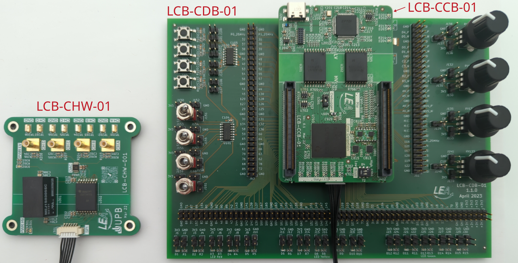
The LEA Control Board (LCB) is a construction kit to provide power electronic converters with a control board.
The basic module is the control board (LCB-CCB) itself. It contains a powerful dual-core processor, error latches and various predefined low-pass filters to respond to input signals. An XDS100v2 debugger is directly integrated on the board.
The docking board (LCB-CDB) is suitable for initial operation. This contains various input options (switches, buttons, potentiometers) as well as LEDs for output.
The external hardware monitor (LCB-CHW) is for viewing internal counter variables on the oscilloscope and is mainly used for troubleshooting the control board in the overall system (control board + power converter).
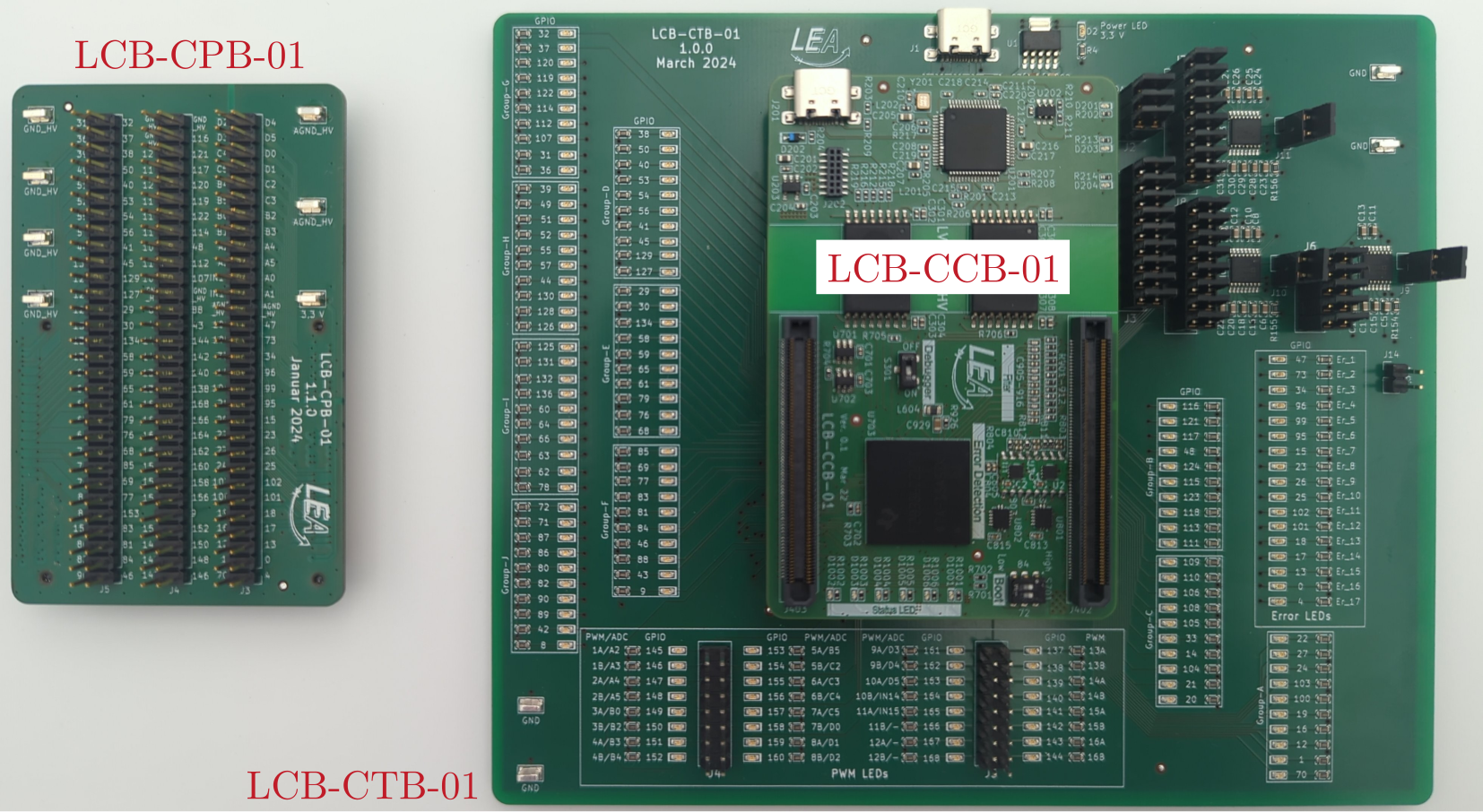
The pin board (LCB-CPB) is for in-circuit signal measurments by an external scope on certain pins. The test board (LCB-CTB) was developed to check all pins, PWM signals, ADCs and DACs for functionality after a new board has been completed (end of line test).
This is the main repository of the LEA Control Board (LCB) project. Due to correct PCB versioning, every single PCB is in its own repository.
Symbols, footprints and 3D-models can be found in the LEA KiCad Library.
Example LCB-CCB-01-1.0.5:
LCB: Parent project name LEA Control BoardCCB: PCB name Control Board01: PCB size. For future use in case of several PCB sizes1: Major version, increases for incompatible changes0: PCB release, increases for improved layouts5: Schematic version, increases for component changes, but no layout changesTo open the LEA Control Board files, KiCad 9 needs to be used. Make sure that you run the latest version of KiCad.
To use this project, LEA KiCad symbols, footprints and 3D-models need to be included. Note, that both folders need to be in the same direction.
Clone the symbols, footprints and 3D-models:
git clone https://github.com/upb-lea/LEA_KiCad_Library.gitClone this project:
https://github.com/upb-lea/LCB-CCB-01_LEA_Control_Board.gitIf you are downloading the .zip-files manually, unpack them in the same direction.
The libraries are included by default, if the above mentioned folder structure was considered. Open Kicad, load one of the projects and see the libraries:
symbol editor -> Search for LEA_Symbol_Libraryfootprint editor -> Search for LEA_Footprint_Library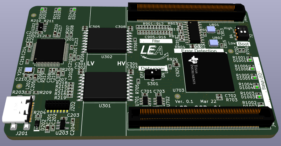 Please refer to this section.
Various software examples using the LEA Control Board is available and can be found in this repository. There are examples for using the hardware monitor, SPI, UART and many others.
| Qty | Value | Footprint | References |
|---|---|---|---|
| 41 | 100n | LEA_FootprintLibrary:C_0603 | C206, C208, C209, C210, C211, C212, C213, C214, C215, C217, C218, C219, C220, C221, C222, C223 +25 |
| 20 | 1k0 | LEA_FootprintLibrary:R_0603 | R801, R802, R803, R804, R809, R810, R811, R812, R913, R914, R915, R916, R917, R918, R919, R920 +4 |
| 16 | 100p | LEA_FootprintLibrary:C_0603 | C801, C804, C807, C810, C905, C906, C909, C910, C913, C914, C917, C918, C921, C922, C925, C926 |
| 15 | 0R0 | LEA_FootprintLibrary:R_0603 | R206, R209, R222, R301, R302, R601, R704, R712, R713, R714, R820, R821, R822, R823, R925 |
| 15 | 100n | LEA_FootprintLibrary:C_0402 | C706, C707, C710, C711, C713, C714, C716, C718, C719, C720, C722, C723, C726, C727, C730 |
| 12 | 1k0 | LEA_FootprintLibrary:R_0805 | R901, R902, R903, R904, R905, R906, R907, R908, R909, R910, R911, R912 |
| 12 | 1n0 | LEA_FootprintLibrary:C_0603 | C907, C908, C911, C912, C915, C916, C919, C920, C923, C924, C927, C928 |
| 12 | Fiducial_medium | LEA_FootprintLibrary:Fiducials_medium | O901, O902, O903, O904, O905, O906, O907, O908, O909, O910, O911, O912 |
| 11 | 2k2 | LEA_FootprintLibrary:R_0603 | R201, R205, R207, R208, R211, R223, R701, R702, R703, R705, R706 |
| 9 | 2u2 | LEA_FootprintLibrary:C_0603 | C301, C304, C305, C308, C603, C604, C605, C607, C608 |
| 9 | 4k7 | LEA_FootprintLibrary:R_0603 | R203, R204, R220, R221, R224, R805, R806, R813, R814 |
| 9 | 680R | LEA_FootprintLibrary:R_0603 | R202, R213, R214, R1001, R1002, R1003, R1004, R1005, R1006 |
| 7 | 10n | LEA_FootprintLibrary:C_0603 | C202, C203, C702, C802, C805, C808, C811 |
| 5 | 10k | LEA_FootprintLibrary:R_0603 | R210, R807, R808, R815, R816 |
| 5 | 1u0 | LEA_FootprintLibrary:C_0603 | C204, C601, C602, C740, C741 |
| 4 | 150mA | LEA_FootprintLibrary:SOD-323_Panjit | D801, D802, D803, D804 |
| 4 | 2mA | LEA_FootprintLibrary:LED_0603_G | D201, D1001, D1002, D1003 |
| 4 | 33R | LEA_FootprintLibrary:R_0603 | R707, R708, R709, R710 |
| 4 | 4u7 | LEA_FootprintLibrary:C_0603 | C201, C205, C207, C216 |
| 4 | TestPoint_Probe | LEA_FootprintLibrary:TestPoint_Pad_D1.0mm | TP601, TP602, TP603, TP604 |
| 3 | ADG736BRMZ | LEA_FootprintLibrary:MSOP10_AnalogDevices | U204, U205, U206 |
| 2 | 2mA | LEA_FootprintLibrary:LED_0603_B | D203, D204 |
| 2 | 2mA | LEA_FootprintLibrary:LED_0603_R | D1005, D1006 |
| 2 | 60R/3A5 | LEA_FootprintLibrary:L_0603 | L601, L603 |
| 2 | 74HC74PW | LEA_FootprintLibrary:TSSOP-14-Nexperia | U801, U802 |
| 2 | CAS-120TA | LEA_FootprintLibrary:CAS-120TA | S201, S301 |
| 2 | ERF5-075-05.0-L-DV-TR | LEA_FootprintLibrary:ERF5-075-05.0-L-DV | J402, J403 |
| 2 | ERM5-075-05.0-L-DV-K-TR | LEA_FootprintLibrary:ERM5-075-05.0-L-DV | J501, J502 |
| 2 | Ferrite_0603 | LEA_FootprintLibrary:L_0603 | L201, L202 |
| 2 | ISO_ISO7741FQDWWQ1 | LEA_FootprintLibrary:SOIC-16_TI_DWW0016A_Optimized | U301, U302 |
| 2 | SYM_LEA_Logo | LEA_FootprintLibrary:SYM_lea_logo | SYM901, SYM902 |
| 2 | TLV3202AIDGKR | LEA_FootprintLibrary:VSSOP-8-TI | U803, U804 |
| 1 | 10R | LEA_FootprintLibrary:R_0603 | R715 |
| 1 | 12k | LEA_FootprintLibrary:R_0603 | R217 |
| 1 | 1A0 | LEA_FootprintLibrary:SOD-323_Infineon | D202 |
| 1 | 22u | LEA_FootprintLibrary:C_0603 | C929 |
| 1 | 2mA | LEA_FootprintLibrary:LED_0603_Y | D1004 |
| 1 | 56R | LEA_FootprintLibrary:R_0603 | R711 |
| 1 | 74ALVC08PW | LEA_FootprintLibrary:TSSOP-14-Nexperia | U805 |
| 1 | 93LC56BT-I_OT | LEA_FootprintLibrary:SOT-23-6_Microchip | U202 |
| 1 | ECS-2033-120-AU | LEA_FootprintLibrary:Osc_ECS_2.5x2 | Y201 |
| 1 | ECS-2520S33-250-FN-TR | LEA_FootprintLibrary:Osc_ECS_2.5x2 | Y701 |
| 1 | FT2232HL | LEA_FootprintLibrary:LQFP-64_12x12_Pitch0.5mm_FTDI | U201 |
| 1 | FTR-110-03-G-D-06-TR | LEA_FootprintLibrary:FTR-110-03-G-D-06 | J202 |
| 1 | LOGO | LOGO | G*** |
| 1 | M3_MountingHole | LEA_FootprintLibrary:MountingHole_M3 | H201 |
| 1 | MAX6037AAUK30+T | LEA_FootprintLibrary:SOT-23-5_Microchip | U901 |
| 1 | MIC5259-3.3YD5-TR | LEA_FootprintLibrary:SOT-23-5_Microchip | U203 |
| 1 | MIC5504-1.2YM5-TR | LEA_FootprintLibrary:SOT-23-5_Microchip | U601 |
| 1 | Molex_532617006 | LEA_FootprintLibrary:6-PinHeader_Molex_532617006 | J401 |
| 1 | PI6C49CB04AQ3WEX | LEA_FootprintLibrary:SOIC-8 | U704 |
| 1 | SW_Push_RightAngle | LEA_FootprintLibrary:Sw_Push_RightAngle | SW701 |
| 1 | TMS320F28388D | LEA_FootprintLibrary:BGA-361_19x19_16.0x16.0mm | U703 |
| 1 | TPS3702CX12DDCT | LEA_FootprintLibrary:TSOT-23-6_TI | U702 |
| 1 | TPS3702CX33DDCT | LEA_FootprintLibrary:TSOT-23-6_TI | U701 |
| 1 | USBC_GTC_USB4110-GF-A | LEA_FootprintLibrary:USB_C_GCT_USB4110-GF-A | J201 |

open-dynamic-robot-initiative/open-motor-driver-initiative
Open-source drive for brushless motors, following the open dynamic robot initiative


antmicro/scalenode-cm4-baseboard
Baseboard for Raspberry Pi 4 Compute Module optimized for clustering

antmicro/cm4-baseboard
Experimental baseboard supporting System on Modules with Raspberry Pi CM4/CM5 pinout

It measures 85 × 55 mm and has 8 copper layers, 2.47 mm thick.
267 parts, built around the PI6C49CB04AQ3WEX, ADG736BRMZ, 74HC74PW and 74ALVC08PW. The full list of its parts is on this page, with links to each part's symbol and footprint where PCBKit's library has them.
From the upb-lea/LCB-CCB-01_LEA_Control_Board repository on GitHub, at the commit this page was made from: the board is LCB-CCB-01/LCB-CCB-01.kicad_pcb and its schematic LCB-CCB-01/AnalogFilter.kicad_sch. PCBKit opens the board in the browser, with nothing to install.
Its repository states no licence, so its author keeps all rights: ask upb-lea before reusing the design.