4 layers71.8 × 54.6 mm

 united-ecology/btmboard5
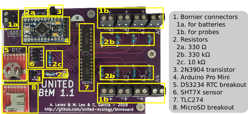
This project is an Arduino based datalogger for monitoring moss conductance as well as environmental humidity and temperature. Up to eight moss and/or lichen samples can be logged in parallel using a single BtMboard.
BtMusgo is an open-source printed circuit board by united-ecology, from the united-ecology/btmboard repository on GitHub. It is a 2-layer board of 123 × 82.7 mm with 36 parts on 40 nets, routed with 426 tracks and 70 vias.
It is built around the TLC274ID, SHT71 and LM1117-3.3. Its parts include 19 resistors, 4 ICs, 4 connectors, 2 transistors and 1 capacitor. It belongs with the AVR (ATmega, ATtiny) boards of this library.


This project is an Arduino based datalogger for monitoring moss conductance as well as environmental humidity and temperature. Up to eight moss and/or lichen samples can be logged in parallel using a single BtMboard. If you are interested in using it, do not hesitate to contact :)
This repository is associated with the following publication: Leo, M., Lareo, A., Garcia-Saura, C., Hortal, J., Medina, N. G. BtM, a Low-cost Open-source Datalogger to Estimate the Water Content of Nonvascular Cryptogams. J. Vis. Exp. (145), e58700, doi:10.3791/58700 (2019).
A video with further instructions on how to build and use the datalogger can be found in the paper link: BtM, a Low-cost Open-source Datalogger to Estimate the Water Content of Nonvascular Cryptogams. Notice that version 1.0 was used in the recording, and it might slightly differ from the current version.
Do not switch off the datalogger while measuring (LED light on). It can be switched off safely during the sleeping period (LED light off).
This software folder contains the source code needed to use the BtM datalogger. Make sure you choose the appropriate board (Pro Mini 328 3.3V) in the Arduino IDE.
Libraries contains the libraries needed for the datalogger. Copy them to your local Arduino IDE installation in the /libraries folder.
Clock contains a project to set up the date / hour of the BtM datalogger. It will set it according to your local system clock.
Datalog contains the main project used to log the data. The sampling frequency can be controlled here by modifying interval (sleeping period in seconds). Make sure you select the appropriate sensor (SHT7x / SHT85). See this documentation on how to do it.
The hardware folder contains the KiCAD project files for the BtM PCB Board. See the List of Components section for details about the hardware needed to assembly the board.
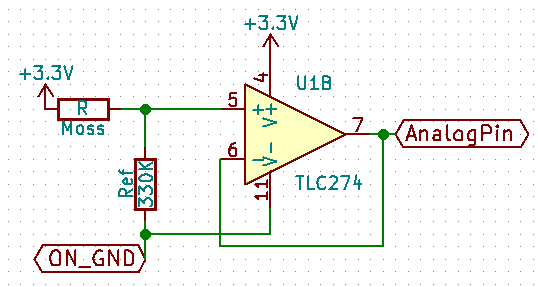
As shown in the image, a voltage divider between each sample (Moss) and a resistor reference (Ref) with a known value (330KΩ in our case) is used to calculate the conductance measure. Probes are applied to each moss/lichen sample. Reference resistor value must be selected through calibration and based on previous measures of the cryptogams. It provides a resolution of one order of magnitude around the reference value (in our case, 100 – 1000 KΩ).
| Qty | Value | Footprint | References |
|---|---|---|---|
| 9 | R | Resistors_THT:R_Axial_DIN0207_L6.3mm_D2.5mm_P10.16mm_Horizontal | R2, R7, R8, R9, R10, R15, R16, R17, R18 |
| 5 | MountingHole_3.2mm_M3_Pad_Via | Mounting_Holes:MountingHole_3.2mm_M3_Pad_Via | , , , , |
| 2 | 2N3904 | TO_SOT_Packages_THT:TO-92_Inline_Wide | Q1, Q2 |
| 2 | TLC274 | Housings_DIP:DIP-14_W7.62mm_LongPads | U1, U2 |
| 1 | 10k | Resistors_THT:R_Axial_DIN0207_L6.3mm_D2.5mm_P10.16mm_Horizontal | R19 |
| 1 | 330 | Resistors_THT:R_Axial_DIN0207_L6.3mm_D2.5mm_P10.16mm_Horizontal | R1 |
| 1 | ArduinoProMini | mysensors_arduino:pro_mini | IC1 |
| 1 | CP | Capacitors_THT:CP_Radial_D10.0mm_P5.00mm | C1 |
| 1 | LM1117-3.3 | Power_Integrations:TO-220 | U3 |
| 1 | Musgo0 | TerminalBlocks_Phoenix:TerminalBlock_Phoenix_MKDS1.5-2pol | R14 |
| 1 | Musgo1 | TerminalBlocks_Phoenix:TerminalBlock_Phoenix_MKDS1.5-2pol | R5 |
| 1 | Musgo2 | TerminalBlocks_Phoenix:TerminalBlock_Phoenix_MKDS1.5-2pol | R6 |
| 1 | Musgo3 | TerminalBlocks_Phoenix:TerminalBlock_Phoenix_MKDS1.5-2pol | R3 |
| 1 | Musgo4 | TerminalBlocks_Phoenix:TerminalBlock_Phoenix_MKDS1.5-2pol | R4 |
| 1 | Musgo5 | TerminalBlocks_Phoenix:TerminalBlock_Phoenix_MKDS1.5-2pol | R12 |
| 1 | Musgo6 | TerminalBlocks_Phoenix:TerminalBlock_Phoenix_MKDS1.5-2pol | R13 |
| 1 | Musgo7 | TerminalBlocks_Phoenix:TerminalBlock_Phoenix_MKDS1.5-2pol | R11 |
| 1 | Power | TerminalBlocks_Phoenix:TerminalBlock_Phoenix_MKDS1.5-2pol | J1 |
| 1 | RTC | Socket_Strips:Socket_Strip_Straight_1x07_Pitch2.54mm | J3 |
| 1 | SHT71 | Socket_Strips:Socket_Strip_Straight_1x04_Pitch2.54mm | J4 |
| 1 | microSD | Socket_Strips:Socket_Strip_Straight_1x07_Pitch2.54mm | J2 |
The 35 most common of 36 parts.

SpintroniK/eXaDrums-pcb
Kicad files of the board that connects eXaDrums to a Roland TD4-KP kit.


acidbourbon/MCP4461_logpot_testboard
KiCAD project files for MCP4461 test board and FFT analysis script. Read the article on https://acidbourbon.wordpress.com/2016/10/01/brute_force_logpots


maelmitc/Peau_Artificielle
$${\color{black}Objectif\space\color{black}du\space\color{black}projet\color{black}}$$ Ce projet à pour but d'appliqué à un robot déjà conçu (REACHY) une interface tactile dans le but de lui permettre d'interragir…
It measures 123 × 82.7 mm and has 2 copper layers, 1.6 mm thick.
36 parts, built around the TLC274ID, SHT71 and LM1117-3.3. The full list of its parts is on this page, with links to each part's symbol and footprint where PCBKit's library has them.
From the united-ecology/btmboard repository on GitHub, at the commit this page was made from: the board is Hardware/BtMusgo.kicad_pcb and its schematic Hardware/BtMusgo.kicad_sch. PCBKit opens the board in the browser, with nothing to install.
Its repository states no licence, so its author keeps all rights: ask united-ecology before reusing the design.