
2 layers18.5 × 11.1 mm
Switch
byrantech/laptop
anyon_e, a highly integrated, high end, open source laptop. Attempt the impossible.
6 parts4.3kMIT

 ulfmagnetics/midi-thing
MIDI breakout board for the Expert Sleepers Disting Mk4
Midi thing is an open-source printed circuit board by ulfmagnetics, from the ulfmagnetics/midi-thing repository on GitHub. It is a 2-layer board of 18 × 60 mm with 6 parts on 6 nets, routed with 31 tracks and 0 vias.
It belongs with the audio and music and interfaces and adapters boards of this library.
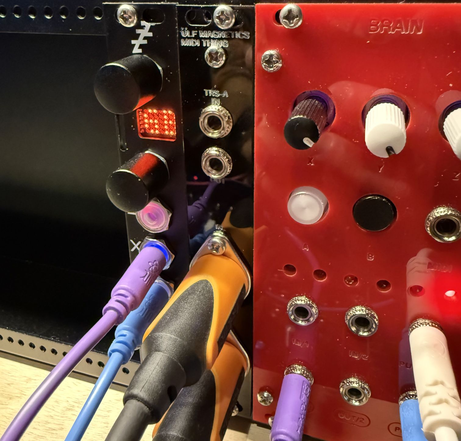
The MIDI Thing is an I/O breakout board for the Expert Sleepers Disting mk4. It provides two 5-pin DIN jacks and two TRS-A jacks that allow you to connect MIDI devices to the Disting. It's a fully passive 4HP module (no power required, no current draw).
The "MIDI I/O" section (page 120) of the Disting Mk4 manual (PDF) says:
A passive breakout module which exposes the MIDI ports as 5-pin DIN sockets is available (also in kit form). See this page. A 3.5mm TRS jack version is also available – see this page.
As of January 2026 I was unable to find any existing stock for these boards, so I decided to design one for myself as a way to learn more about PCB design and Eurorack module development. You should be able to find all the files and build instructions you'll need to make one of these modules for yourself on this page.
I was heavily inspired by the Shmoerg Moduleur project's approach to PCB fabrication and documentation for this project - it's no coincidence that I built a Moduleur for myself a few weeks before designing the MIDI Thing! If you're interested in fully-DIY projects like this, definitely have a look at the Moduleur. I learned a lot while building it!
I used OSH Park for this. The project is here; should have everything you need to order the boards for around $8-10 + shipping. If you prefer JLBPCB or another vendor, see the Files section below for links to the Gerbers etc that you'll need to upload.
See What you'll need above for the materials required. Note that the only components required are the two 5-pin DIN jacks for MIDI I/O (Mouser), and the stereo 3.5mm jacks for TRS-A I/O (Thonk). Everything else you might either have lying around from other projects if you're like me, or you can source easily from Adafruit or Amazon.
The MIDI DIN jacks are panel-mounted in this design, so you'll need the faceplate at this point. I've included the SVG that I imported into Lightburn to cut it out of 1/8" acrylic at my local maker space. Remember to use separate layers for the etched text and the cuts!
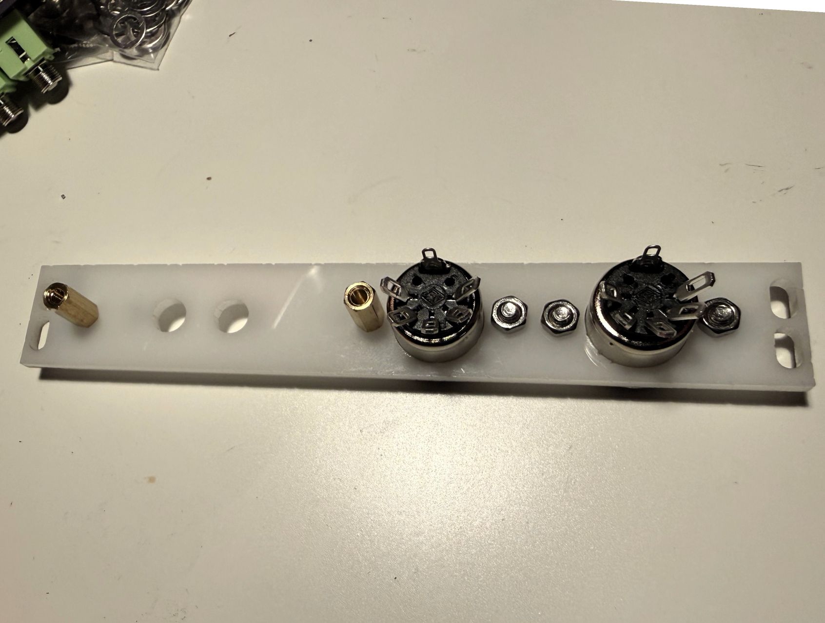
Once you have the faceplate, attach the DIN jacks with the M3 10mm screws and nuts, as well as the 10mm standoffs that will hold the PCB. Note that the topmost of the four screws (the top screw of the MIDI IN jack) connects to a standoff rather than an M3 nut to save vertical space on the panel.
At this point you should heat up the soldering iron and solder the 4-pin header (J1) onto the back of the PCB, i.e. the side opposite the silkscreened logo. The long pins of the header need to extend out the back of the module so they can be wired up to the Disting's GT2 header once everything is done.
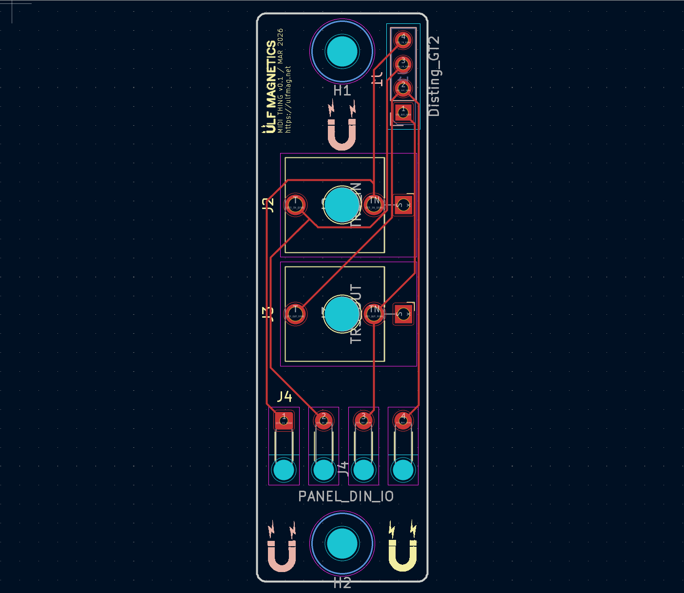
Solder the two stereo Thonkiconn jacks (you got the green ones, right?!) onto J2 and J3 on the front of the PCB.
Cut four lengths of our 26-28AWG wire, preferably in different colors, cut them to maybe 3" in length, and strip and tin the ends. For each length of wire, push one end through the strain relief hole from the front to the back of the PCB and solder the end to the corresponding J4 pad from the back. Hopefully the following photo will help a bit:
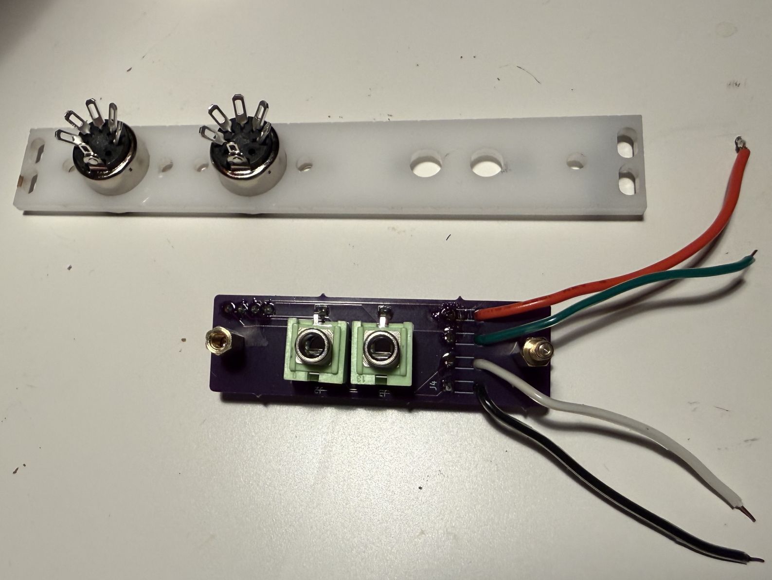
The trailing ends of these wires will be soldered to the DIN jacks in the next step.
Mount the PCB to the faceplate via the 10mm standoffs, and using the Thonkiconn washers and nuts to hold the jacks firmly in place.
Now take a deep breath and prepare for the fussiest part of the assembly, which is soldering the J4 wires to the lugs on the DIN jacks. The 57GB5FX datasheet will be helpful here:
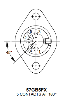
Because MIDI uses a digital current loop there is no need to ground the DIN or 3.5mm jacks, and we'll only use pins 4 and 5 of the DIN jacks (and only the tip and ring connections from the 3.5mm stereo jacks).
First, figure out which color of wire needs to go to which lug. Making a table with pen and paper is extremely helpful here. If you want to go straight to the source you can download KiCAD and open up the PCB layout, or just take my word for it that the pads should be connected as follows:
| J4 Pad # | In/Out | 57GB5FX Pin |
|---|---|---|
| 1 | In | 4 |
| 2 | In | 5 |
| 3 | Out | 4 |
| 4 | Out | 5 |
For each wire, figure out which lug should be the destination, keeping in mind that the lugs will be on the opposite side when you view the jack from the back (4 on the right, 5 on the left). Trim the wire to an appropriate length, leaving some slack to reduce strain on the connection, then trim the wire, wrap it around the lug, and solder it in place.
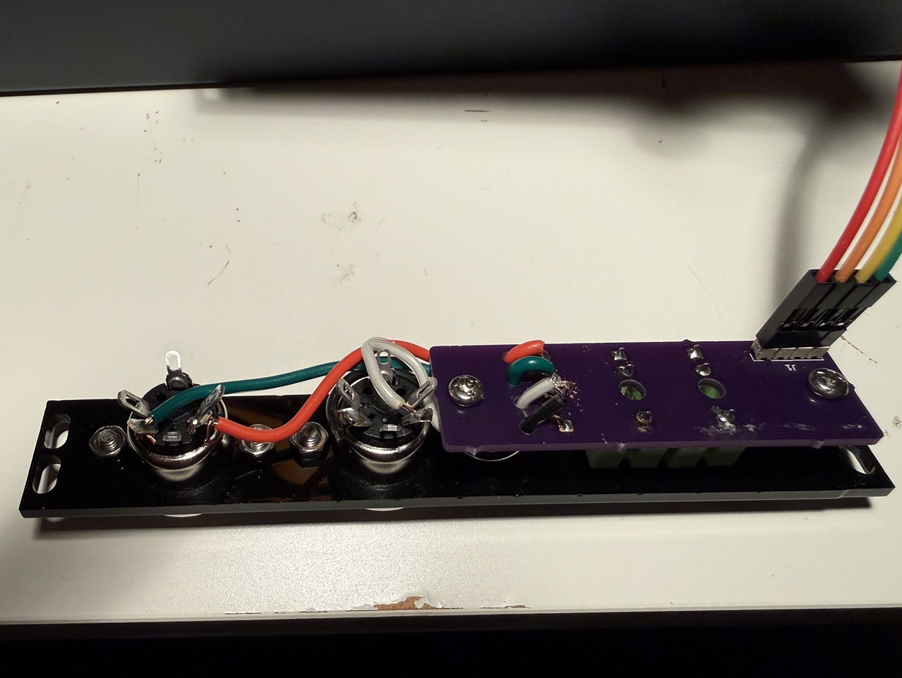
Finally connect the Dupont wire (or 4-wire ribbon cable) to the J1 header.
Almost done now! Next you'll want to connect the wires from the J1 header on the MIDI Thing to the corresponding wire on the Disting's GT2 header. You'll need to remove the Disting from your rack first.
The pin numbers on the MIDI Thing match up with those on the GT2, so keeping in mind that pin 1 is identified by a square on the silkscreen, just connect each wire in sequential order (pin 1 -> pin 1, pin 2 -> pin 2, etc.)
Put everything back into the rack and test that the module is working as expected. I used algorithm G-7 (MIDI/CV) to test the MIDI in ports, and G-8 (CV/MIDI) to test MIDI out.
electronics/KiCad project files — schematic and PCB layout.
| File | Description |
|---|---|
midi_thing.kicad_sch | Schematic |
midi_thing.kicad_pcb | PCB layout |
midi_thing.kicad_pro | KiCad project |
faceplate/Panel design for laser cutting.
| File | Description |
|---|---|
midi_thing-faceplate.svg | Faceplate SVG |
production/Gerbers and drill file for PCB fabrication (OSH Park ready).
| File | Description |
|---|---|
midi_thing-gerbers.zip | All gerbers + drill file, zipped for upload |
midi_thing.drl | Drill file |
midi_thing-*.gbr | Individual Gerber layers (F/B copper, mask, silkscreen, edge cuts) |
| Qty | Value | Footprint | References |
|---|---|---|---|
| 1 | Disting_GT2 | Connector_PinHeader_2.54mm:PinHeader_1x04_P2.54mm_Vertical | J1 |
| 1 | H1 | MountingHole:MountingHole_3.2mm_M3 | H1 |
| 1 | H2 | MountingHole:MountingHole_3.2mm_M3 | H2 |
| 1 | PANEL_DIN_IO | Ulf_Magnetics:SolderWire-0.25sqmm_1x04_P4.2mm_D0.65mm_OD1.7mm_Relief | J4 |
| 1 | TRS_IN | Ulf_Magnetics:Thonkiconn_Stereo | J2 |
| 1 | TRS_OUT | Ulf_Magnetics:Thonkiconn_Stereo | J3 |
byrantech/laptop
anyon_e, a highly integrated, high end, open source laptop. Attempt the impossible.


Jcparkyn/dpoint
Open-source digital stylus using camera tracking and inertial measurements

VoronDesign/Voron-Hardware
Cool Hardware designed by the Voron Design group

hoglet67/RGBtoHDMI
Bare-metal Raspberry Pi project that provides pixel-perfect sampling of Retro Computer RGB/YUV video and conversion to HDMI

hackclub/OnBoard
💡 Join 1,000 teenagers and make your first PCB with a $100 grant!

Luos-io/luos_engine
Open-source and real-time orchestrator for cyber-physical-systems, to easily design, test and deploy embedded applications and digital twins.

It measures 18 × 60 mm and has 2 copper layers, 1.6 mm thick.
6 parts. The full list of its parts is on this page, with links to each part's symbol and footprint where PCBKit's library has them.
From the ulfmagnetics/midi-thing repository on GitHub, at the commit this page was made from: the board is electronics/midi_thing.kicad_pcb and its schematic electronics/midi_thing.kicad_sch. PCBKit opens the board in the browser, with nothing to install.
Its repository states no licence, so its author keeps all rights: ask ulfmagnetics before reusing the design.