2 layers112.6 × 85.4 mm

 ulbo/5x16segment
Linkable 5x16 segment LED display
16segment is an open-source printed circuit board by ulbo, from the ulbo/5x16segment repository on GitHub, published under the GPL-3.0 licence. It is a 2-layer board of 100 × 60 mm with 54 parts on 64 nets, routed with 930 tracks and 42 vias.
It is built around the ATMEGA16A-AU and BC817-40. Its parts include 23 resistors, 8 capacitors, 5 diodes, 5 transistors and 5 connectors. It belongs with the lEDs and displays boards and the AVR (ATmega, ATtiny) boards of this library.


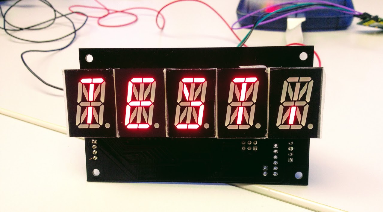 Single display board
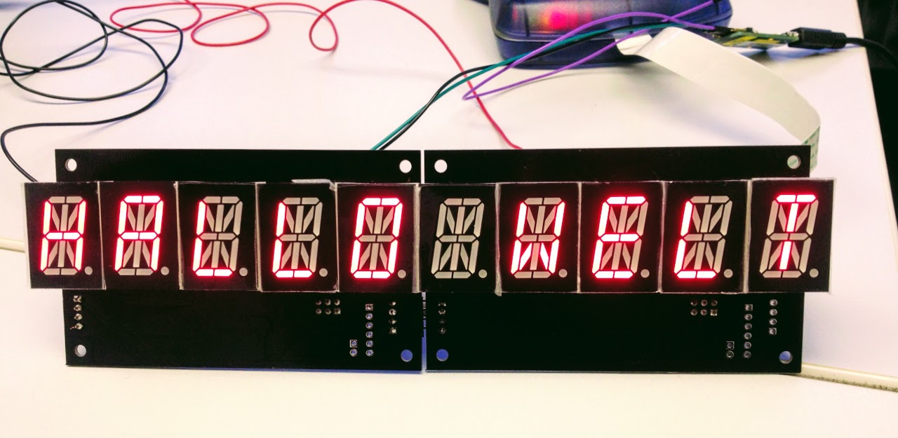 Two boards connected to form a 10 character display
The module uses an Atmel ATmega32 MCU to control all LED segments. Input is done via RS232 interface with a voltage level of 5V.
Supply voltage: 5VDC, max. 200mA per module
Board layout is designed using KiCAD. It is tested for LDS8103-AX 16-segment displays (see /board/lds-8103.jpg), but should work with any common-cathode 16-segment display with same mechanical dimensions and pinout, e.g. Kingbright PSC08-11GWA. Because all pins, except the cathode at pin 11, are directly controlled by the MCU, LEDs with other pinouts can be used with adapted firmware.
Please note: The LED displays are soldered on the opposite board site than the ATmega.
Communication to modules is unidirectional with 9600 bps, 8N1. Modules are daisy-chained, the RS232 output of the leftmost module is connected to the input of its right neighbour. Every module displays all incoming ASCII characters. If its 5-character memory is full, it passes all further incoming chars to its output, where it is received by the next display.
There are a few control characters, which are always passed immediately:
Compilation under Windows by Atmel Studio 7, Project file: /firmware/16segment.atsln For Linux, /firmware/makefile is provided, see instructions there.
Firmware is flashed using the standard 6-pin ISP connector. File is /firmware/Release/16segment.hex
Fuse settings:
| Qty | Value | Footprint | References |
|---|---|---|---|
| 17 | 180 | Resistors_SMD:R_0603_HandSoldering | R2, R3, R4, R5, R6, R7, R8, R10, R11, R12, R13, R14, R15, R16, R17, R18 +1 |
| 5 | 100nF | Capacitors_SMD:C_0603_HandSoldering | C3, C4, C5, C6, C7 |
| 5 | 470 | Resistors_SMD:R_0603_HandSoldering | R19, R20, R21, R22, R23 |
| 5 | BC817-40 | TO_SOT_Packages_SMD:SOT-23_Handsoldering | Q1, Q2, Q3, Q4, Q5 |
| 5 | LDS-8103AX | LDS8103-AX:LDS8103-AX_rev | LED1, LED2, LED3, LED4, LED5 |
| 2 | 15pF | Capacitors_SMD:C_0805_HandSoldering | C1, C2 |
| 1 | 10k | Resistors_SMD:R_0603_HandSoldering | R1 |
| 1 | 10uF | Capacitors_SMD:C_1210_HandSoldering | C8 |
| 1 | 16 MHz | Crystals:Q_49U3HMS | X1 |
| 1 | ATMEGA16-A | Housings_QFP:TQFP-44_10x10mm_Pitch0.8mm | IC1 |
| 1 | AVR ISP | Pin_Headers:Pin_Header_Straight_2x03 | P2 |
| 1 | CONN_01X02 | Pin_Headers:Pin_Header_Straight_1x02 | P5 |
| 1 | CONN_01X06 | Pin_Headers:Pin_Header_Straight_1x06 | P1 |
| 1 | DATA_IN | Pin_Headers:Pin_Header_Angled_1x04 | P3 |
| 1 | DATA_OUT | Pin_Headers:Pin_Header_Angled_1x04 | P4 |
The 48 most common of 54 parts.
It measures 100 × 60 mm and has 2 copper layers, 1.6 mm thick.
54 parts, built around the ATMEGA16A-AU and BC817-40. The full list of its parts is on this page, with links to each part's symbol and footprint where PCBKit's library has them.
From the ulbo/5x16segment repository on GitHub, at the commit this page was made from: the board is board/16segment.kicad_pcb. PCBKit opens the board in the browser, with nothing to install.
Its repository publishes it under the GPL-3.0 licence: you may reuse it on that licence's terms (keep the author's notice, and for a copyleft licence share your changes alike).


vedantjadhav304/Atmega32_DEV_BOARD
Open source AVR embedded system development board based on Atmega32


pcb-firmware-embedded/Atmega16A_temperature_monitoring
This repository contains the complete development of a temperature monitoring and alarm system based on the ATmega16A microcontroller.


elektra42/freifunk-open-mppt
Open hard- and software solar maximum power point tracker