Skip to the content
PCBKitNew board
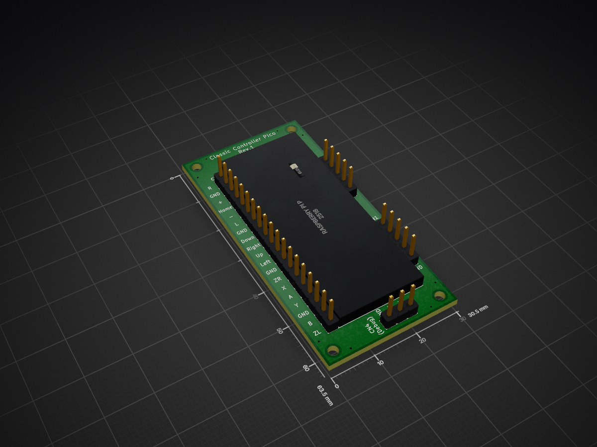
2 layers30.5 × 63.5 mmClassicControllerPico, the printed circuit board in 3D

ClassicControllerPico

tt3333/ClassicControllerPico4

Classic Controller Pico is a program that allows Raspberry Pi Pico to be recognized as Wii classic controller.

Size
30.5 × 63.5 mm
Copper layers
2
Thickness
1.6 mm
Parts
12
Nets
32
Pads
82
Tracks, vias
56, 17
Pours
1
Routed
Yes
KiCad
KiCad 6 (file 20211014)
Created
29 Aug 2023
Updated
24 Mar 2024

Overview

ClassicControllerPico is an open-source printed circuit board by tt3333, from the tt3333/ClassicControllerPico repository on GitHub, published under the GPL-3.0 licence. It is a 2-layer board of 30.5 × 63.5 mm with 12 parts on 32 nets, routed with 56 tracks and 17 vias.

Its parts include 4 connectors, 2 resistors, 1 IC and 1 diode. It belongs with the RP2040 boards of this library.

README

README.md

日本語版 README はこちら

Classic Controller Pico

Classic Controller Pico is a program that allows Raspberry Pi Pico to be recognized as Wii classic controller.

This project is based off of the Wii RetroPad Adapter project by Bruno Freitas.
The license for this project follows the license for the Wii RetroPad adapter.

Tested Hardware

How to Build Hardware

Ordering PCBs

If you place an order with JLCPCB and want the order number printed in an inconspicuous location

Upload gerber_JLCPCB.zip and select "Specify a location" from the "Remove Order Number" options.

If you place an order with JLCPCB and do not want the order number printed

Upload gerber.zip and select "Yes" from the "Remove Order Number" options.
However, if Yes is selected, an optional fee will be charged.

For orders outside of JLCPCB

Upload gerber.zip.

Assembly

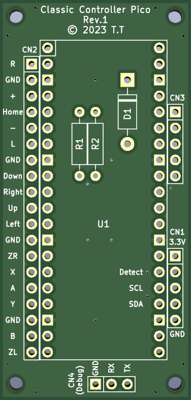
  • Solder 2kΩ resistors to R1 and R2.
    (Built-in pull-up resistors in Raspberry Pi Pico are too high in resistance, so communication is not stable without external pull-up resistors.)
  • Solder a Schottky barrier diode (1N5819) to D1.
  • Solder sockets to U1 and mount a Raspberry Pi Pico.
  • Cut the extension cable for Wii in half and connect the Male cable to CN1.
  • Connect buttons of your choice to each terminals of CN2.
  • At this time, CN3 does not need to be connected to anything.
    (A future version may support analog stick connection.)
  • CN4 is for debugging firmware, so normally nothing needs to be connected.
  • While pressing the BOOTSEL button on the Raspberry Pi Pico, connect the USB cable and write the firmware.ino.uf2.

PCB

Example of Use

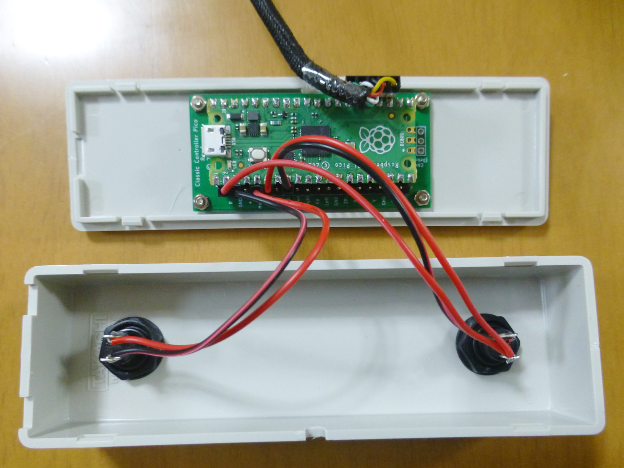
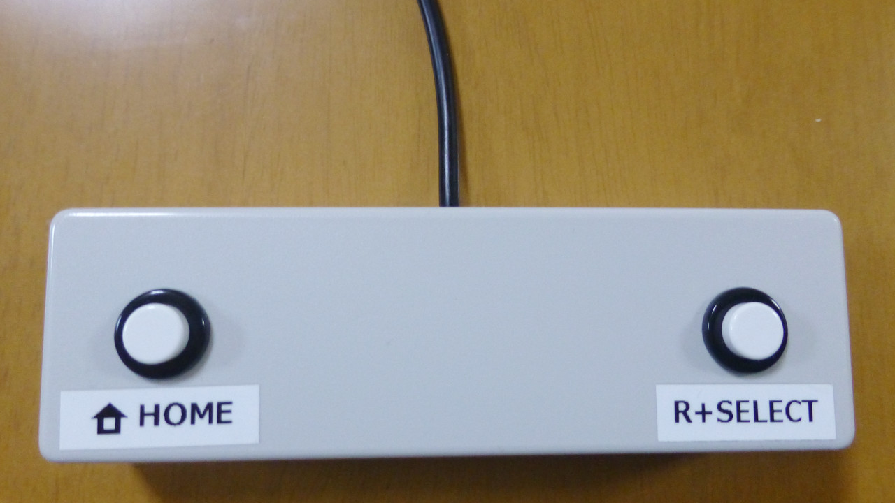
This is an example of two MS-350Ms from Marushin electric mfg. installed on a SW-130 from TAKACHI ELECTRONICS ENCLOSURE.
Pin headers are used so that button assignments can be easily changed by simply replacing the connectors.
Note the following points because the case is just barely high enough when the connectors is inserted into the pin headers.

  • When ordering PCBs from JLCPCB, I chose 0.8mm for "PCB Thickness" instead of the standard 1.6mm. (I made it as thin as possible without incurring any additional charges.)
  • By using a nuts instead of spacers and securing the board between the nut and nut, the gap between the board and case is reduced to one nut.
  • To reduce the protrusion of the backside of the board, not only resistors and diodes but also the pins of IC sockets and pin headers are cut short.
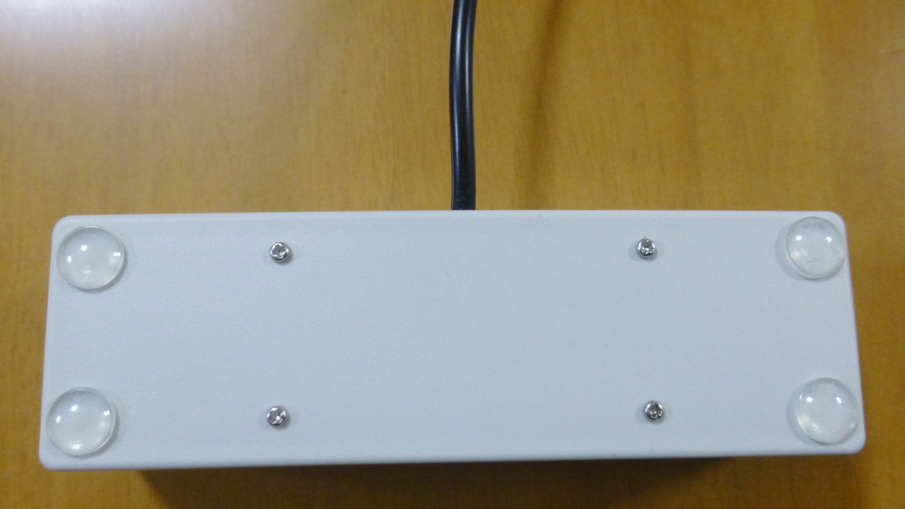
  • Rubber cushions are attached to the back surface to prevent slipping when operating with the feet.

assembly top bottom

If you modify firmware

If you connect a USB serial converter to CN4 and enable #define DEBUG in config.h, debug output is available.

How to Build Firmware

  1. Install Arduino IDE
  2. Open firmware.ino
  3. Click "File", then "Preferences..."
  4. Copy and paste the following URL into the "Additional boards manager URLs" field and click "OK"
    https://github.com/earlephilhower/arduino-pico/releases/download/global/package_rp2040_index.json
  5. Click "Tools", "Board", then "Board Manager..."
  6. Type "pico" in the search field and install "Raspberry Pi Pico/RP2040 by Earle F. Philhower, III"
  7. Click "Tools", "Board", "Raspberry Pi Pico/RP2040", then "Raspberry Pi Pico"
  8. Click "Tools", "Optimize", then "Fast (-Ofast) (maybe slower)"
  9. Click "Sketch", then "Export Compiled Binary"

Parts

12
QtyValueFootprintReferences
22KLibrary:R_Axial_DIN0207_L6.3mm_D2.5mm_P10.16mm_HorizontalR1, R2
11N5819Diode_THT:D_DO-41_SOD81_P10.16mm_HorizontalD1
1Analog StickLibrary:PinHeader_1x05_P2.54mm_VerticalCN3
1ButtonsLibrary:PinHeader_1x19_P2.54mm_VerticalCN2
1Raspberry Pi PicoLibrary:RPi_Pico_SMD_THU1
1UART (for Debug)Library:PinHeader_1x03_P2.54mm_VerticalCN4
1Wii RemoteLibrary:PinHeader_1x05_P2.54mm_VerticalCN1

The 8 most common of 12 parts.

Questions

How big is the ClassicControllerPico PCB?

It measures 30.5 × 63.5 mm and has 2 copper layers, 1.6 mm thick.

What parts does the ClassicControllerPico use?

12 parts. The full list of its parts is on this page, with links to each part's symbol and footprint where PCBKit's library has them.

Where can I download the ClassicControllerPico KiCad files?

From the tt3333/ClassicControllerPico repository on GitHub, at the commit this page was made from: the board is KiCad/ClassicControllerPico.kicad_pcb and its schematic KiCad/ClassicControllerPico.kicad_sch. PCBKit opens the board in the browser, with nothing to install.

Can I use the ClassicControllerPico design in my own project?

Its repository publishes it under the GPL-3.0 licence: you may reuse it on that licence's terms (keep the author's notice, and for a copyleft licence share your changes alike).

Similar boards

  • 2 layersNrf bga, the printed circuit board in 3D

    Nrf bga

    github-linguist/linguist

    Language Savant. If your repository's language is being reported incorrectly, send us a pull request!

    12 parts14kMIT
  • 2 layers66.9 × 74.5 mmDeskHop, the printed circuit board in 3D

    DeskHop

    hrvach/deskhop

    Fast Desktop Switching Device

    12 parts7.9kGPL-3.0
  • 2 layers40 × 15 mmSensors, the printed circuit board in 3D

    Sensors

    google/mozc-devices

    Circuit diagrams and firmware source code for Gboard DIY keyboards

    12 parts3kApache-2.0
  • 2 layers42.7 × 56.5 mmTle6240 driver, the printed circuit board in 3D

    Tle6240 driver

    rusefi/rusefi

    rusefi - GPL internal combustion engine control unit

    12 parts1.2k
  • 2 layers49 × 25 mm5v boost regulator, the printed circuit board in 3D

    5v boost regulator

    hackclub/OnBoard

    💡 Join 1,000 teenagers and make your first PCB with a $100 grant!

    12 parts915
  • 2 layers28.3 × 10.3 mmTap Photosensor PCB, the printed circuit board in 3D

    Tap Photosensor PCB

    VoronDesign/Voron-Tap

    Tap is a nozzle-based z-probe for the V2 and Trident printer designs. The entire toolhead moves to trigger an optical switch. Tap offers many advantages:

    12 parts716GPL-3.0
  • 2 layers25.4 × 70.4 mmTpmsniffer, the printed circuit board in 3D

    Tpmsniffer

    stacksmashing/pico-tpmsniffer

    A simple, very experimental TPM sniffer for LPC bus

    12 parts696