2 layers78 × 66.5 mm
RAM adapter
trwgQ26xxx/FLT_module_reader
Fiat Lancia Tester modules reader for ROMs preservation
23 parts2

 trwgQ26xxx/FLT_module_reader2
Fiat Lancia Tester modules reader for ROMs preservation
ROM reader is an open-source printed circuit board by trwgQ26xxx, from the trwgQ26xxx/FLT_module_reader repository on GitHub. It is a 2-layer board of 94 × 57.5 mm with 49 parts on 74 nets, routed with 474 tracks and 43 vias.
It is built around the ATMEGA128A-AU and CH340G. Its parts include 16 capacitors, 14 resistors, 5 connectors, 4 diodes and 2 ICs. It belongs with the AVR (ATmega, ATtiny) boards of this library.


Dedicated module reader for FLT\ART\CU-1 ROMs archiving.
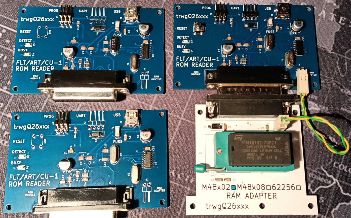
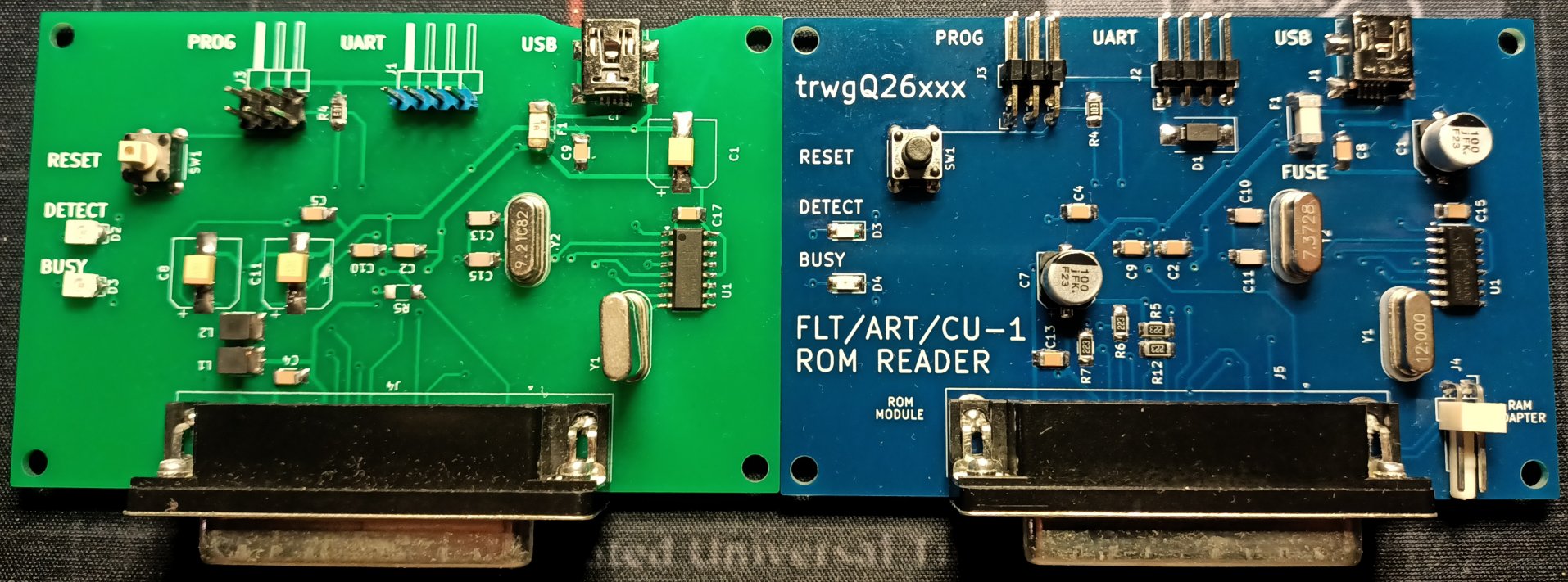
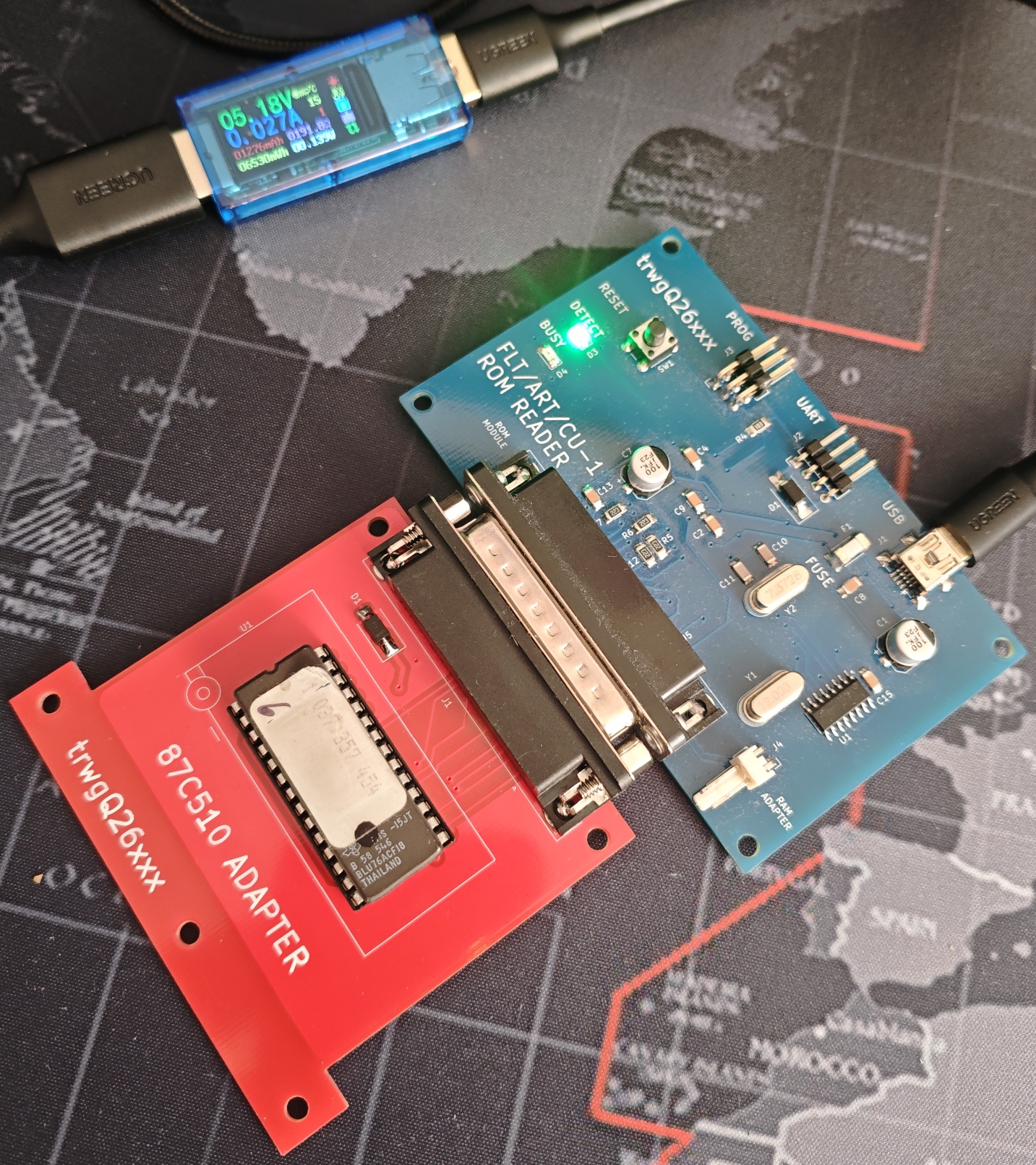
Contact : trwgQ {leechers not welcome} 26 {remove spaces} xxx {remove spaces} {at} proton {dot} me
I do not consent to the use of all or part of the project for commercial purposes!
Nie wyrażam zgody na wykorzystanie całości bądź części projektu w celach zarobkowych!
Shield: 
This work is licensed under a Creative Commons Attribution-NonCommercial-ShareAlike 4.0 International License.

| Windows | Linux | macOS |
|---|---|---|
| reader COM[number] | ./reader /dev/ttyUSB[number] | ./reader /dev/wchusbserial[number] |
For example:
| Windows | Linux | macOS |
|---|---|---|
| reader COM1 | ./reader /dev/ttyUSB0 | ./reader /dev/wchusbserial300 |
where /dev/wchusbserial300 (on macOS), /dev/ttyUSB0 (on Linux) or COM1 (on Windows) should be actual serial port name of connected ROM reader.
The ROM reader uses the CH340 serial chip, which can be identified by the VID/PID values of 1A86/7523, respectively.

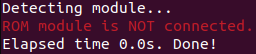
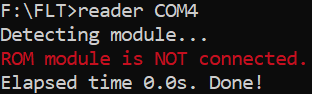
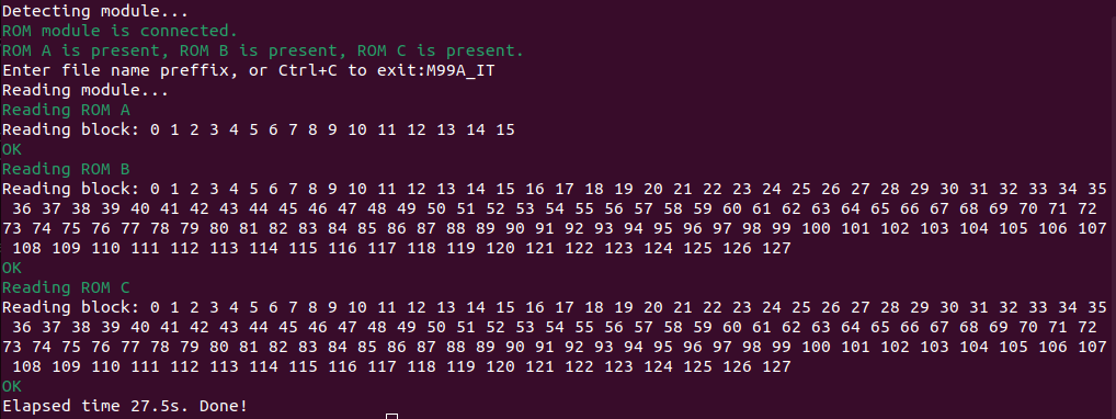
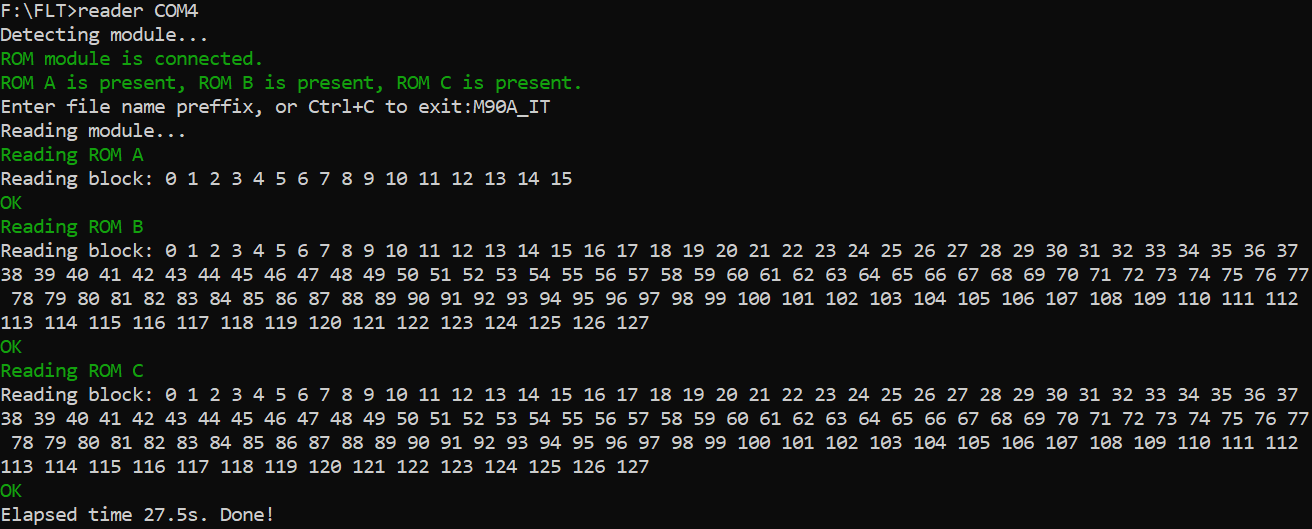
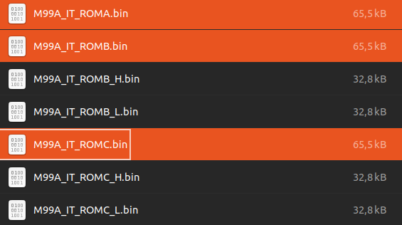
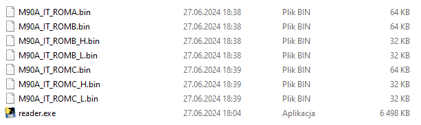
The process is similar for other modules. Here is an example if the module contains only ROM A and B:
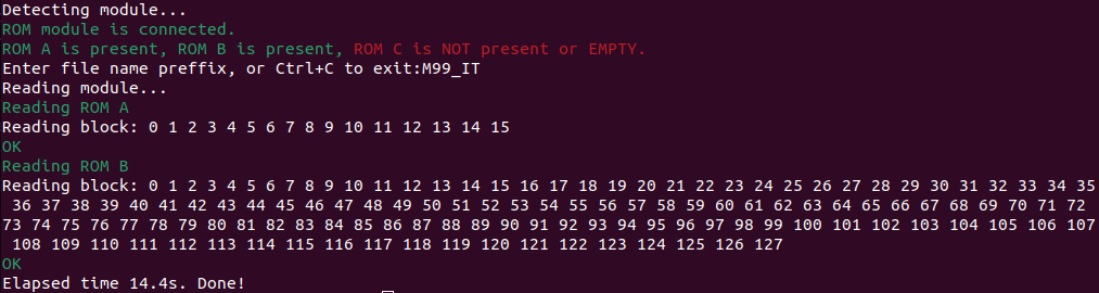
or ROM B only:
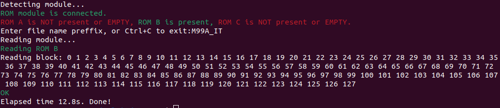
The program reads the contents of only the ROMs that are present in the module.
The RAM adapter is used for SRAM testing. It was primarily constructed to test the M48Z02 (used in FLT/ART) and the M48T02 (used in CU-1). The RAM adapter takes the form of a standard FLT ROM module. Additionally, it requires a connection to a supplementary 2-pin connector with the #WR signal, which is not present on the DSUB-25 connector of the ROM.
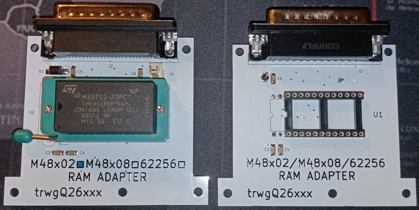
Before usage, the RAM adapter must be configured to the correct RAM variant using solder bridges (SB1 - SB3) on the PCB. The configuration is as follows:
| RAM | Size | SB1 | SB2 | SB3 |
|---|---|---|---|---|
| M48T02, M48T12, M48Z02 and M48Z12 | 2kB | OFF | 1-2 | 1-2 |
| M48T08, M48T18, M48Z08 and M48Z18 | 8kB | OFF | 1-2 | 2-3 |
| 62256 | 32kB | ON | 2-3 | 2-3 |
The supported commands are:
This command tests the SRAM battery and SRAM memory. The supported SRAM types (ram_type) for this command are:
| ram_type | Size | Type |
|---|---|---|
| M48T02 | 2kB | battery-backed SRAM with RTC |
| M48Z02 | 2kB | battery-backed SRAM |
| M48T08 | 8kB | battery-backed SRAM with RTC |
| M48Z08 | 8kB | battery-backed SRAM |
| S62256 | 32kB | SRAM |
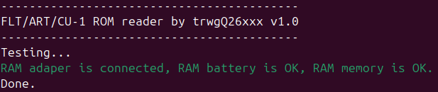
Executes an RTC-specific command. The command (command) can be:
| command | Description |
|---|---|
| start | Starts the internal oscillator and enables normal clock operation. |
| stop | Stops the internal oscillator, which saves battery power if the SRAM is left on the shelf for an extended period. |
| set | Sets the current time. |
| reset | Resets all registers, stops the internal oscillator, and sets the time to 0:0:0 on 1-1-2000. |
The supported SRAM types for this command are:
| ram_type | Size | Type |
|---|---|---|
| M48T02 | 2kB | battery-backed SRAM with RTC |
| M48T08 | 8kB | battery-backed SRAM with RTC |
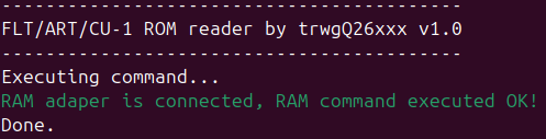
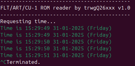
Retrieves the time from the SRAM RTC and prints it on the screen in an infinite loop at a rate of twice per second. Use Ctrl-C to stop the execution of this command.
The supported SRAM types for this command are:
| ram_type | Size | Type |
|---|---|---|
| M48T02 | 2kB | battery-backed SRAM with RTC |
| M48T08 | 8kB | battery-backed SRAM with RTC |
Execute the reset command to reset the RAM clock.
Execute the start command* to starts the internal oscillator and enable normal clock operation.
Execute the set command to set the current time.
Run RAM_clock_read to verify both the validity of the time and that it increments. If both conditions are met, the RTC is functioning properly.
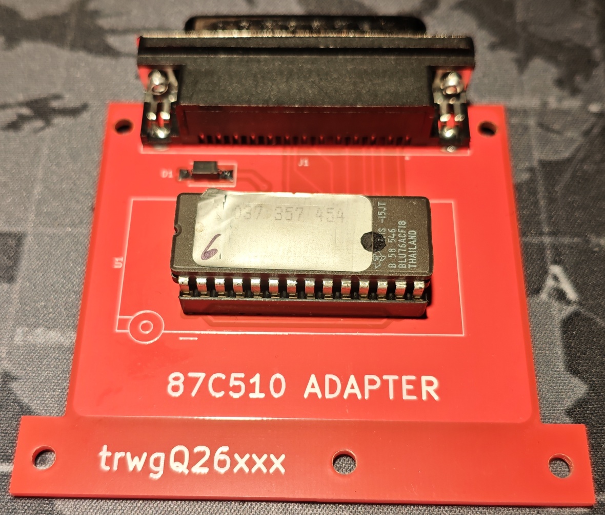
The 87C510 adapter is designed for reading ROMs used in certain Bosch Motronic ECUs. The TMS87C510 is a 64 KB UV-erasable, multiplexed EPROM that supports both 8-bit and 16-bit output modes. The adapter is implemented in the form of a standard FLT ROM module, with the 87C510 configured and wired as ROMB.
Atmega64A fusebits should be configured as follows:
| Extended | High | Low |
|---|---|---|
| 0xFE | 0xC9 | 0x1F |
| Qty | Value | Footprint | References |
|---|---|---|---|
| 10 | 100n | Capacitor_SMD:C_1206_3216Metric_Pad1.33x1.80mm_HandSolder | C2, C3, C5, C8, C9, C10, C11, C12, C13, C16 |
| 8 | 22k | Resistor_SMD:R_1206_3216Metric_Pad1.30x1.75mm_HandSolder | R2, R3, R4, R5, R6, R7, R8, R9 |
| 4 | 22p | Capacitor_SMD:C_1206_3216Metric_Pad1.33x1.80mm_HandSolder | C6, C7, C14, C15 |
| 4 | MH | MountingHole:MountingHole_3.2mm_M3_DIN965 | H1, H2, H3, H4 |
| 2 | 100u | Capacitor_SMD:CP_Elec_6.3x7.7 | C1, C4 |
| 2 | 10k | Resistor_SMD:R_1206_3216Metric_Pad1.30x1.75mm_HandSolder | R1, R10 |
| 2 | 2k2 | Resistor_SMD:R_1206_3216Metric_Pad1.30x1.75mm_HandSolder | R11, R12 |
| 2 | 5k1 | Resistor_SMD:R_1206_3216Metric_Pad1.30x1.75mm_HandSolder | R13, R14 |
| 1 | 0.5A | Fuse:Fuse_2512_6332Metric_Pad1.52x3.35mm_HandSolder | F1 |
| 1 | 12MHz | Crystal:Crystal_HC49-4H_Vertical | Y2 |
| 1 | 4148 | Diode_SMD:D_SMA_Handsoldering | D1 |
| 1 | 7.3728MHz | Crystal:Crystal_HC49-4H_Vertical | Y1 |
| 1 | ATmega128A-A | Package_QFP:TQFP-64_14x14mm_P0.8mm | U1 |
| 1 | BUSY | LED_SMD:LED_1206_3216Metric_Pad1.42x1.75mm_HandSolder | D4 |
| 1 | CH340G | Package_SO:SOIC-16_3.9x9.9mm_P1.27mm | U2 |
| 1 | DETECT | LED_SMD:LED_1206_3216Metric_Pad1.42x1.75mm_HandSolder | D3 |
| 1 | ISP | Connector_PinHeader_2.54mm:PinHeader_2x03_P2.54mm_Horizontal | J3 |
| 1 | RAM ADAPTER EXT | Connector_PinHeader_2.54mm:PinHeader_1x02_P2.54mm_Horizontal | J2 |
| 1 | ROM MODULE | Connector_Dsub:DSUB-25_Socket_Horizontal_P2.77x2.84mm_EdgePinOffset4.94mm_Housed_MountingHolesOffset4.94mm | J1 |
| 1 | RST | Button_Switch_THT:SW_PUSH_6mm | SW1 |
| 1 | Schottky | Diode_SMD:D_SMB_Handsoldering | D2 |
| 1 | TTL_UART | Connector_PinHeader_2.54mm:PinHeader_1x04_P2.54mm_Horizontal | J4 |
| 1 | USB C SOCKET | Connector_USB:USB_C_Receptacle_GCT_USB4105-xx-A_16P_TopMnt_Horizontal | J5 |
trwgQ26xxx/FLT_module_reader
Fiat Lancia Tester modules reader for ROMs preservation

trwgQ26xxx/FLT_module_reader
Fiat Lancia Tester modules reader for ROMs preservation

UzixLS/zxevo1010-board
10x10cm PCB variant of ZX-Evolution project for G738/G706 enclosure


MrBruh/Vikings-Robotics-PCB
A board with 2 ATMEGA microprocessors for controlling up to 7 DC motors and 4 servos

cansat-ptl/cubesat-boards
YKTSAT Kicad board files - mirror of https://git.yktaero.space/yktaero-dev/cubesat-boards


jibonaronno/documentsA
It is required to change settings using SCLManager.exe when required for new setup.

It measures 94 × 57.5 mm and has 2 copper layers, 1.6 mm thick.
49 parts, built around the ATMEGA128A-AU and CH340G. The full list of its parts is on this page, with links to each part's symbol and footprint where PCBKit's library has them.
From the trwgQ26xxx/FLT_module_reader repository on GitHub, at the commit this page was made from: the board is PCB/ROM_reader.kicad_pcb and its schematic ADAPTERS/87C510_ADAPTER/87C510_adapter.kicad_sch. PCBKit opens the board in the browser, with nothing to install.
Its repository states no licence, so its author keeps all rights: ask trwgQ26xxx before reusing the design.