Skip to the content
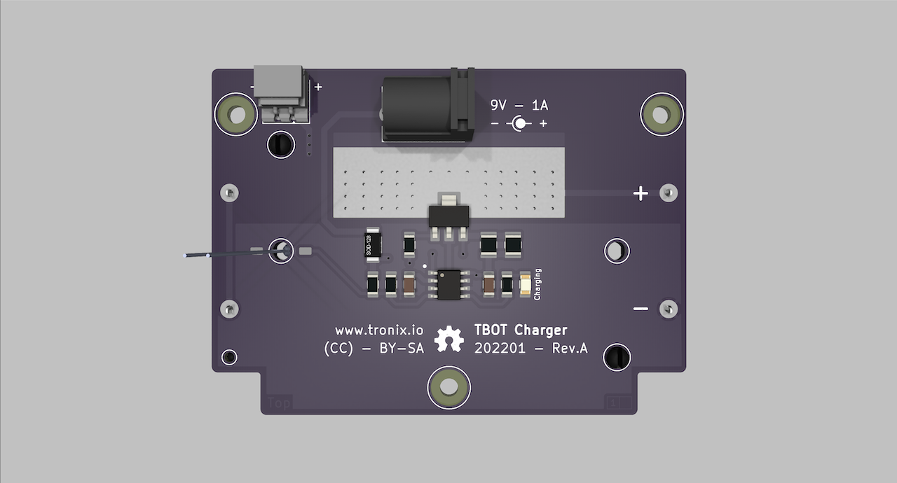
2 layers78 × 57 mmCharger, the printed circuit board in 3D
Size
78 × 57 mm
Copper layers
2
Thickness
1.6 mm
Parts
21
Nets
11
Pads
51
Tracks, vias
56, 53
Pours
4
Routed
Yes
KiCad
KiCad 7 (file 20221018)
Created
13 Dec 2021
Updated
14 Dec 2024

Overview

Charger is an open-source printed circuit board by tronixio, from the tronixio/robot-tbot repository on GitHub. It is a 2-layer board of 78 × 57 mm with 21 parts on 11 nets, routed with 56 tracks and 53 vias.

It is built around the BQ2057WSN, PMEG3030EP and STN790A. Its parts include 6 resistors, 2 capacitors, 2 diodes, 2 switches and 1 IC. It belongs with the power boards of this library.

Main components

3

README

README.md

ROBOT - TBOT 2 Wheels.

TBOT Features.

TBOT All Schematics.

TBOT Code.

TBOT Firmware.

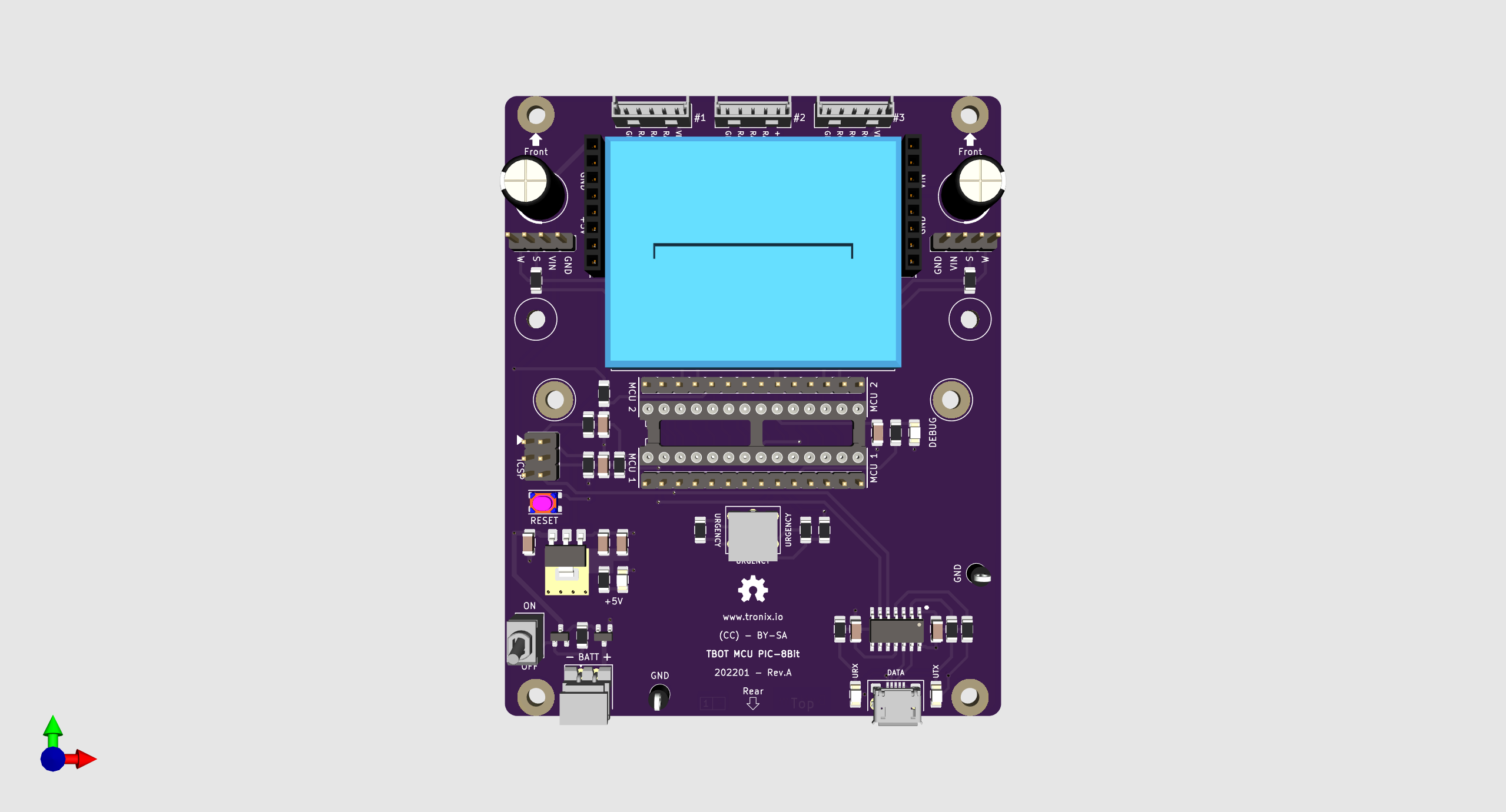
DRAFT - TBOT MCU PIC 8Bit Top.

TBOT MCU PIC 8Bit Top.

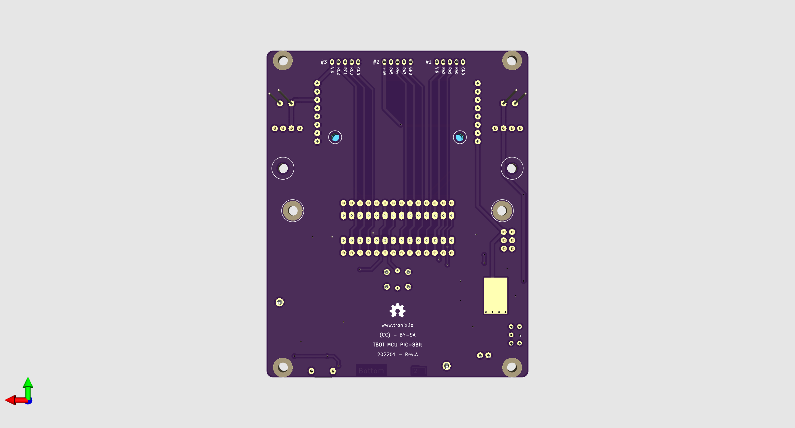
DRAFT - TBOT MCU PIC 8Bit Bottom.

TBOT MCU PIC 8Bit Bottom.

TBOT Charger Top.

TBOT Charger Top.

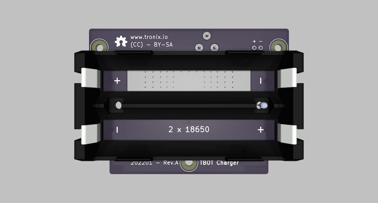
TBOT Charger Bottom.

TBOT Charger Bottom.

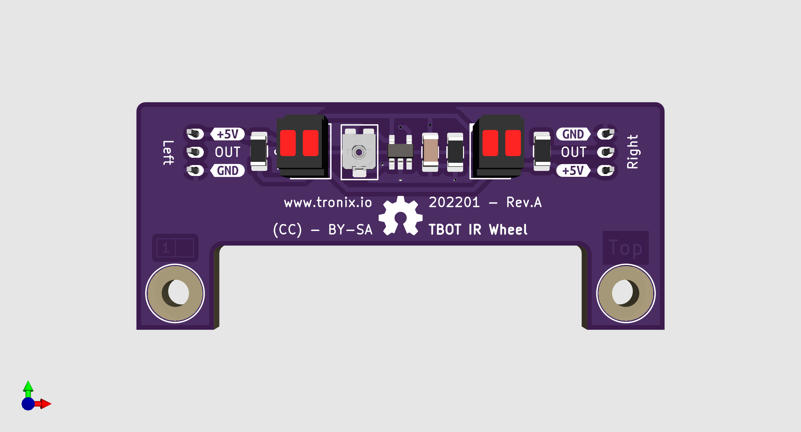
DRAFT - TBOT IR Wheel Top.

TBOT IR Wheel Top.

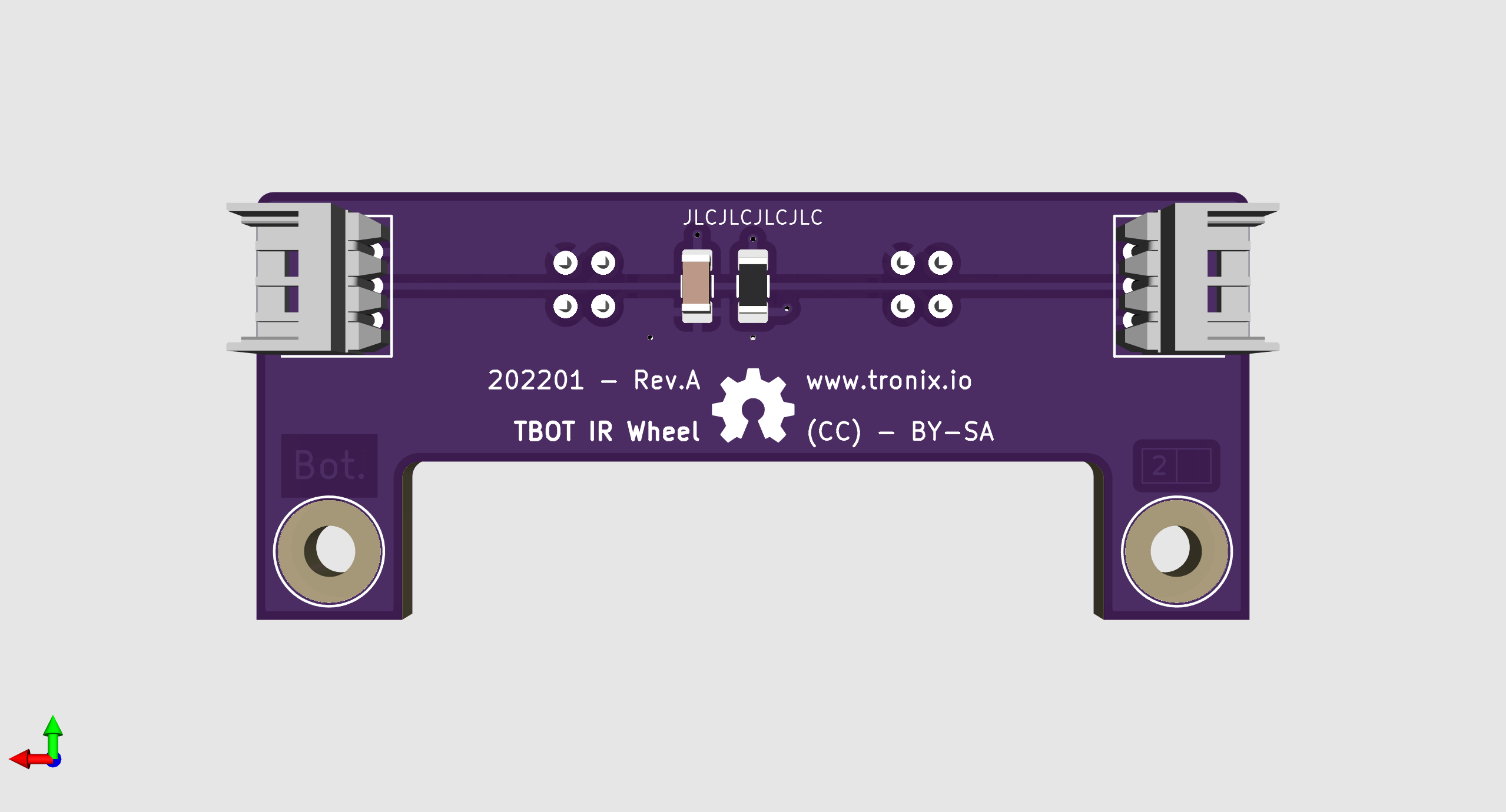
DRAFT - TBOT IR Wheel Bottom.

TBOT IR Wheel Bottom.

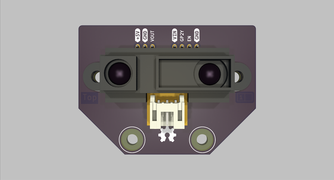
TBOT GP2Y Top.

TBOT GP2Y Top.

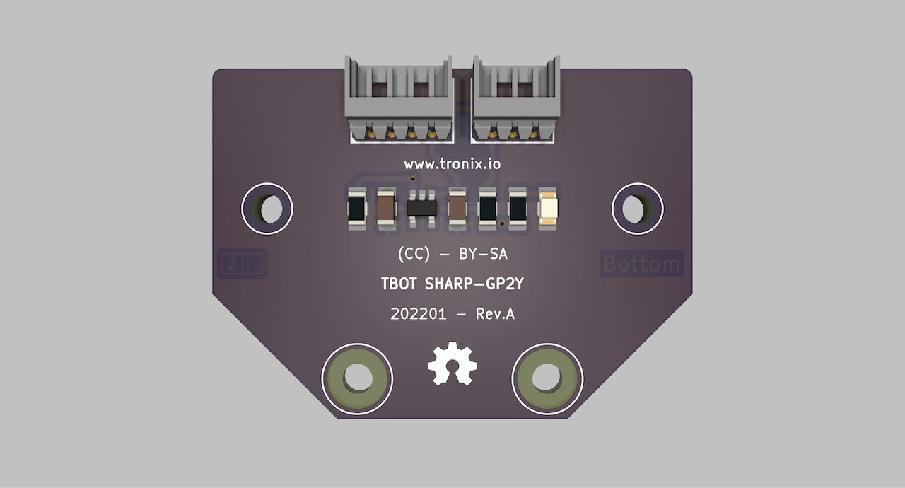
TBOT GP2Y Bottom.

TBOT GP2Y Bottom.

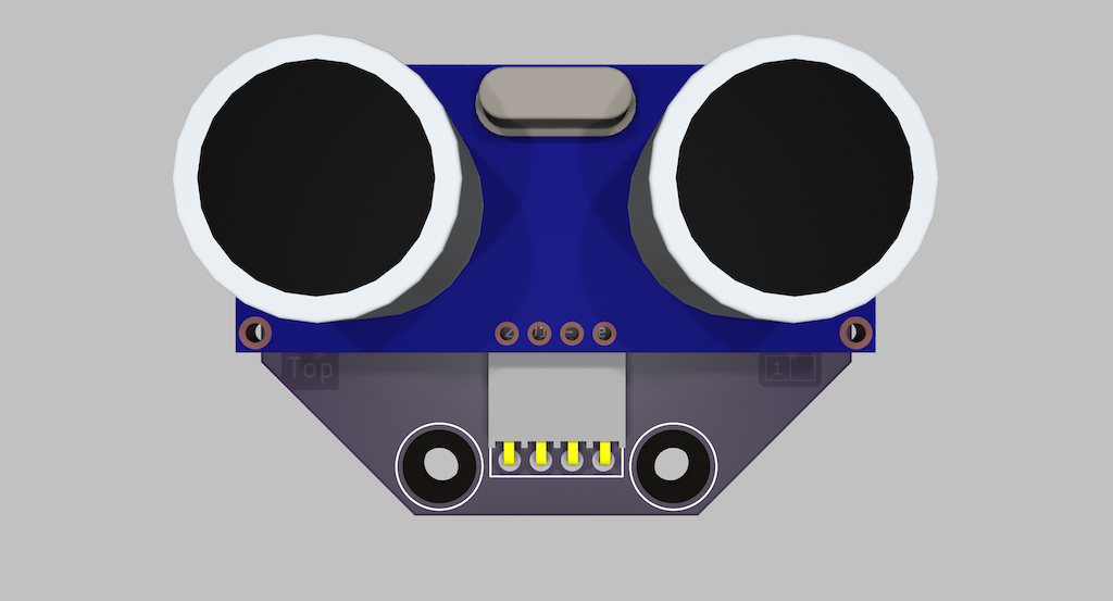
DRAFT - TBOT HC-SR04 Top.

TBOT HC-SR04 Top.

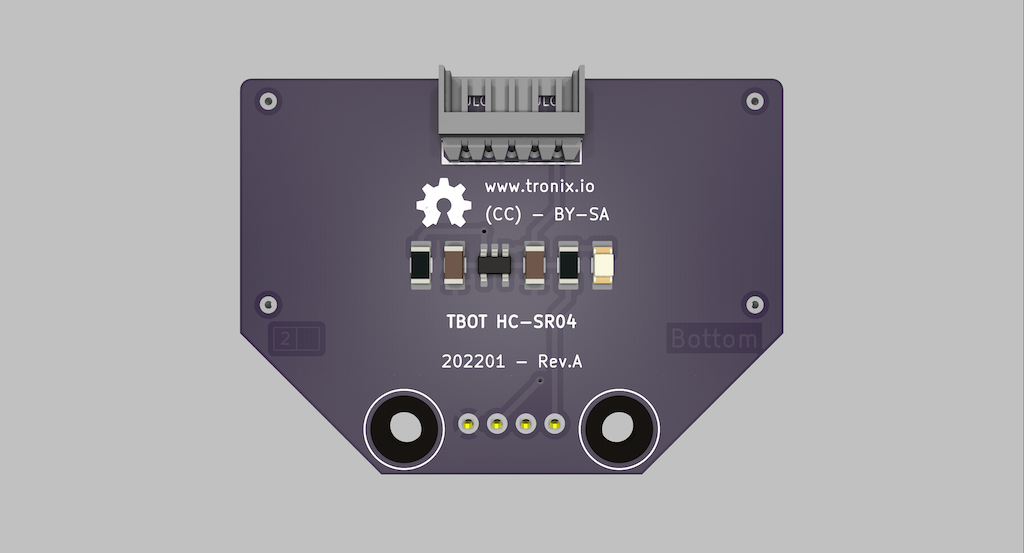
DRAFT - TBOT HC-SR04 Bottom.

TBOT HC-SR04 Bottom.

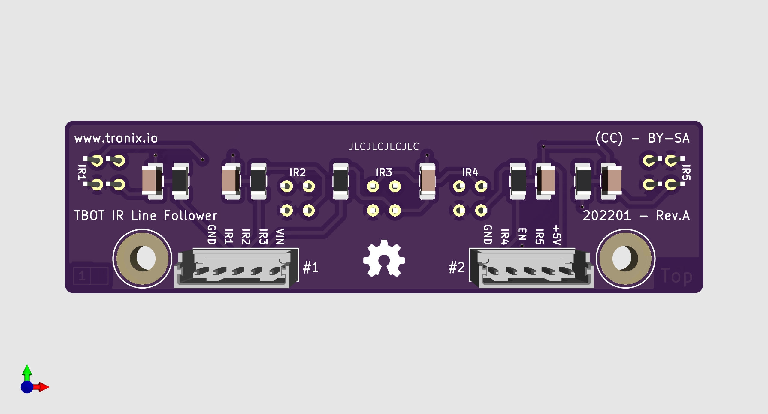
DRAFT - TBOT IR Line Follow Top.

TBOT IR Line Follow Top.

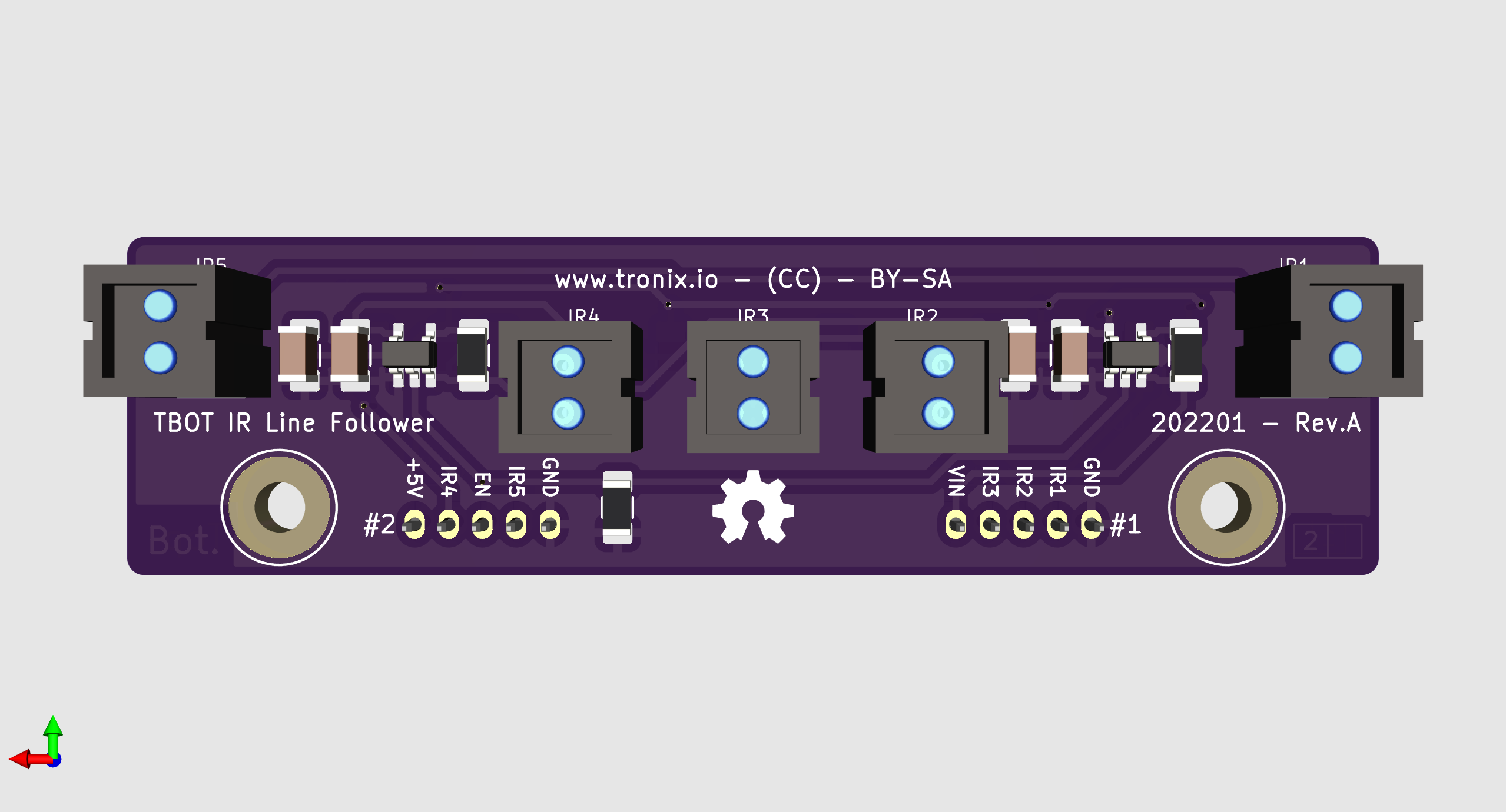
DRAFT - TBOT IR Line Follow Bottom.

TBOT IR Line Follow Bottom.

!!! note

text
- DRAFT : Prototype OK, last check schematic, PCB & code can be modify.
- TODO : Work in progress, prototype was not good, hardware, PCB and code can be rework.

!!! example "DISCLAIMER"

text
THIS CODE IS PROVIDED WITHOUT ANY WARRANTY OR GUARANTEES.
USERS MAY USE THIS CODE FOR DEVELOPMENT AND EXAMPLE PURPOSES ONLY.
AUTHORS ARE NOT RESPONSIBLE FOR ANY ERRORS, OMISSIONS, OR DAMAGES THAT COULD
RESULT FROM USING THIS FIRMWARE IN WHOLE OR IN PART.

Parts

21
QtyValueFootprintReferences
3MOUNTING-HOLE-3MM-MASKtronixio:MOUNTING-HOLE-3MM-MASKH1, H2, H3
20Ω1tronixio:RESISTOR-SMD-1210R2, R3
2LOGOtronixio:OSHW-5MMGB, GT
1100ntronixio:CAPACITOR-SMD-1206C1
110ktronixio:RESISTOR-SMD-1206R5
110ktronixio:THERMISTOR-SMDTH1
118650tronixio:KEYSTONE-1049BT1
11ktronixio:RESISTOR-SMD-1206R4
11µtronixio:CAPACITOR-SMD-1206C2
136ktronixio:RESISTOR-SMD-1206R6
14k7tronixio:RESISTOR-SMD-1206R1
1BQ2057Wtronixio:SOIC-08U1
1Batterytronixio:MOLEX-22057025K2
1Chargertronixio:CUI-PJ-102AHK1
1Chargingtronixio:LED-SMD-1206LED1
1PMEG3030tronixio:SOD-128D1
1STN790Atronixio:SOT-223-3Q1

More from tronixio/robot-tbot

6
  • 2 layers80 × 100 mmTbot-8bit, the printed circuit board in 3D

    Tbot-8bit

    tronixio/robot-tbot

    92 parts
  • 2 layers80 × 100 mmTbot-16bit, the printed circuit board in 3D

    Tbot-16bit

    tronixio/robot-tbot

    63 parts
  • 2 layers74 × 20 mmIr line, the printed circuit board in 3D

    Ir line

    tronixio/robot-tbot

    30 parts
  • 2 layers48 × 35 mmGp2y, the printed circuit board in 3D

    Gp2y

    tronixio/robot-tbot

    18 parts
  • 2 layers48 × 35 mmHc sr04, the printed circuit board in 3D

    Hc sr04

    tronixio/robot-tbot

    15 parts

Similar boards

  • 2 layers80 × 140 mmMotors, the printed circuit board in 3D

    Motors

    tronixio/robot-tcar

    155 parts
  • 6 layers102.6 × 62.6 mmSPANNUNG BLE 1, the printed circuit board in 3D

    SPANNUNG BLE 1

    joeheinz/Tensosense-Schem

    This is my personal design project...

    139 parts
  • 2 layers99.8 × 35 mmLichtobjekt 6, the printed circuit board in 3D

    Lichtobjekt 6

    martinclausen2/Lichtobjekt

    The "Lichtobjekt" projects allows to create portable lighting appliances.

    125 partsGPL-3.0
  • 2 layers100 × 22.8 mmBattery charger, the printed circuit board in 3D

    Battery charger

    UviDTE-UviSpace/pcb-designs

    Printed Circuit Boards (PCBs) for UviSpace

    20 partsGPL-3.0
  • 2 layers55 × 55 mmLeafNode v3.1, the printed circuit board in 3D

    LeafNode v3.1

    leafai-io/leaf-node-v3.x

    Modular node for sensor monitoring and device control in grow environments.

    91 parts47
  • 2 layers50 × 50 mmM5-pantilt, the printed circuit board in 3D

    M5-pantilt

    HeliosH/stackchan-diy-guide

    Stack-chan(スタックチャン)手挫完全指南:国内采购 / PCB 打样 / 3D 打印 / 装配 / 固件全流程教程 + 完整资料(STL / KiCad / 预编译固件)

    39 parts2Apache-2.0
  • 4 layers100 × 65 mmOctaveEnv, the printed circuit board in 3D

    OctaveEnv

    hsetlik/octaveEnv

    Dual octave pedal modulated by an internal envelope follower

    91 parts1
  • 4 layers86.3 × 67.8 mmGuitarProcessorBoard, the printed circuit board in 3D

    GuitarProcessorBoard

    hsetlik/GuitarProcessorH7

    Effect Pedal built on STM32H7

    134 parts

Questions

How big is the Charger PCB?

It measures 78 × 57 mm and has 2 copper layers, 1.6 mm thick.

What parts does the Charger use?

21 parts, built around the BQ2057WSN, PMEG3030EP and STN790A. The full list of its parts is on this page, with links to each part's symbol and footprint where PCBKit's library has them.

Where can I download the Charger KiCad files?

From the tronixio/robot-tbot repository on GitHub, at the commit this page was made from: the board is Kicad/charger/main.kicad_pcb and its schematic Kicad/charger/main.kicad_sch. PCBKit opens the board in the browser, with nothing to install.

Can I use the Charger design in my own project?

Its repository states no licence, so its author keeps all rights: ask tronixio before reusing the design.