2 layers90 × 38 mm
LCD OLinuXino-5TS Rev.B
OLIMEX/OLINUXINO
OLINUXINO is Open Source / Open Hardware, low cost from EUR 24 Linux Industrial grade Single Board Computer capable to operate -25+85C
56 parts1.5k

 Triver1/t-he1
Tot-HE-m is a hall-effect version of GEIGEIGEIST's TOTEM: the same 38-key split layout, scaled to MX spacing, with a linear hall sensor under every switch instead of a mechanical contact.
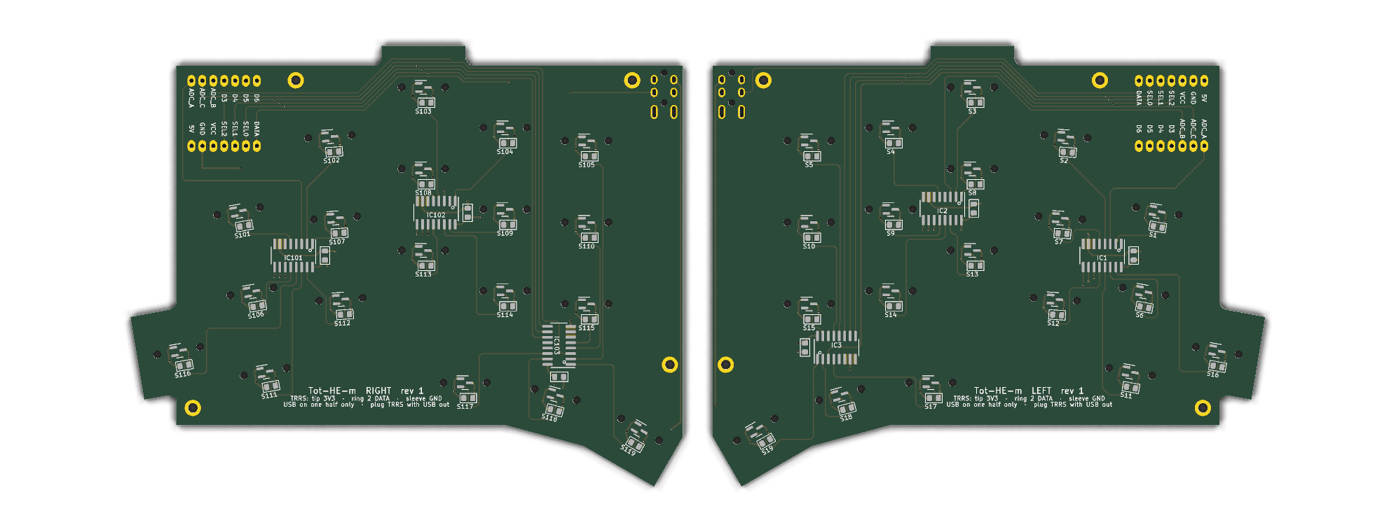
Totem he is an open-source printed circuit board by Triver1, from the Triver1/t-he repository on GitHub. It is a 2-layer board of 264.8 × 103 mm with 56 parts on 56 nets, routed with 1,184 tracks and 46 vias.
Its parts include 38 switches and 6 ICs.
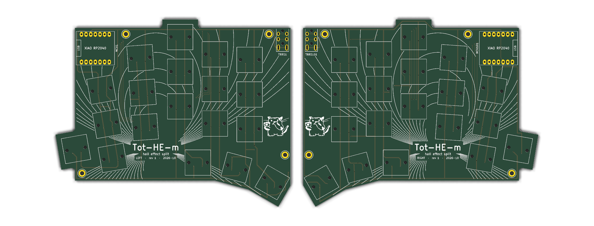
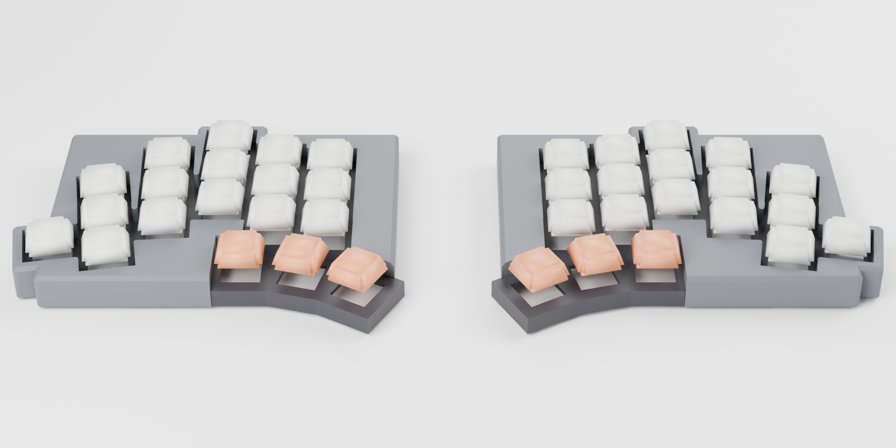
Tot-HE-m is a hall-effect version of GEIGEIGEIST's TOTEM: the same 38-key split layout, scaled to MX spacing, with a linear hall sensor under every switch instead of a mechanical contact. The goal is an analog keyboard that is cheap and easy to build at home. Each half is one two-layer PCB with a handful of SMD parts, a Seeed XIAO RP2040 and a 3D printed case, so everything can be ordered from LCSC, JLCPCB and the usual keyboard shops, and soldered with an ordinary iron.
Rough prices for one keyboard, checked October 2026, in euros, before shipping and taxes. Several parts only come in larger quantities, so ordering for two or more keyboards brings the price per board down a lot.
| Part | Where | Approx. |
|---|---|---|
| PCBs (5 sets) | JLCPCB | 30 |
| Sensors, muxes, capacitors, TRRS jacks | LCSC | 15 |
| 2x Seeed XIAO RP2040 | Seeed or any electronics shop | 15 |
| 38 magnetic switches | keyboard shop | 20 |
| 38 MX keycaps | keyboard shop | 20 |
| TRRS cable, USB-C cable | any | 10 |
| 8x M2 x 10 screws, rubber bumpers | hardware shop | 5 |
| About 150 g of filament | 3 | |
| Total | ≈ 120 |
PCB (JLCPCB). Upload production/Tot-HE-m_gerbers.zip on jlcpcb.com. The
file holds both halves side by side, so an order of 5 gives 5 left and 5 right boards. Settings: 2 layers, 1.6 mm,
1 oz copper, any colour; the defaults cover the rest. JLCPCB counts the two outlines as two designs and adds a small
fee for the second, which shows up in the quote. Pick "Remove order number", or it gets printed on the silkscreen.
Parts (LCSC). On lcsc.com, open the BOM tool, upload production/lcsc_bom.csv and
match the "LCSC Part Number" column. That puts every SMD part and both jacks in the cart in one go, with a few
spares for the small parts:
| Part | LCSC | Per half |
|---|---|---|
| TI DRV5055A3QDBZR linear hall sensor, SOT-23 | C266128 | 19 |
| 74HC4051D analog mux, SOIC-16 | C9386 | 3 |
| 100 nF capacitor, 0805 | C1711 | 22 |
| PJ-320A TRRS jack | C2884926 | 1 |
Everything else: two Seeed XIAO RP2040s, 38 magnetic switches, 38 MX keycaps, a 4-pole TRRS cable, a USB-C cable, eight M2 x 10 screws and at least eight rubber bumpers taller than 2.5 mm.
The cable has to be TRRS (three insulating rings on the plug). A 3-pole TRS cable bridges two contacts in the jack and shorts the 3.3 V supply, and the keyboard stays dark.
Only plug or unplug the TRRS cable with USB disconnected.
The firmware is QMK. Hold the XIAO's BOOT button while plugging a half in; it shows up as a drive called RPI-RP2.
Copy firmware/uf2/tot_he_m_via_left.uf2 onto the left half and tot_he_m_via_right.uf2 onto the
right. Each image stores its side on first boot. Afterwards, hold Esc and press T to get back into the bootloader.
To configure it in VIA:
firmware/via/tot-he-m.json. VIA forgets it when the
browser closes, so load it again next time.The keymap editor then works as on any VIA keyboard, and the Hall effect menu has the analog settings:
| Setting | Range | Default |
|---|---|---|
| Actuation point | 1.0 to 3.8 mm | 2.0 mm |
| Release point | 0.8 mm up to 0.2 mm shallower than actuation | 1.6 mm |
| Rapid trigger | on / off | off |
| Rapid trigger press and release sensitivity | 0.2 to 2.0 mm | 0.3 mm |
| Stick dead zone (controller layer) | 0 to 2.0 mm | 0 |
| Stick full deflection (controller layer) | 0.5 to 4.0 mm | 3.8 mm |
Settings are stored on the half that is plugged in, which sends them to the other half. On Linux, the browser needs
access to the keyboard's hidraw device; a udev rule for vendor 746d, product 7e57 with TAG+="uaccess" does it.
The default keymap follows a Ferris Sweep layout: QWERTY with Ctrl and Alt on the outer bottom keys and, on the thumbs, Shift, Space and Esc on the left, Enter, Backspace and GUI on the right. Holding Backspace gives numbers and symbols, Enter navigation and F-keys, Esc system keys. Hold Esc and press G for the controller layer.
To build the firmware yourself, copy firmware/qmk/tot_he_m into keyboards/ of a QMK checkout and run, for each
half:
qmk compile -kb tot_he_m -km via -e EXTRAFLAGS=-DINIT_EE_HANDS_LEFT -e TARGET=tot_he_m_via_left
qmk compile -kb tot_he_m -km via -e EXTRAFLAGS=-DINIT_EE_HANDS_RIGHT -e TARGET=tot_he_m_via_rightEach half is a shell and a switch plate, both printed without supports: the shell deck-down, the plate top-down.
The stack is the 1.6 mm PCB, the plate 5 mm above it and the deck 6 mm above the plate, 12.6 mm in total. Each
M2 x 10 screw goes up from under the PCB, through the plate's standoff, and cuts its own thread in a pilot hole in
the deck. The screw heads sit under the PCB, so the bumpers need to be taller than 2.5 mm. For a case that gets
opened often, set insert = true in case/totem_he_case.scad to use M2 heat-set inserts instead.
The foam mold casts an optional silicone foam layer between the PCB and the plate, which dampens the sound; the
instructions are at the top of case/foam_mold.scad.
The STLs are in case/stl, made from the OpenSCAD sources (OpenSCAD 2025 or newer):
openscad --enable=roof -D 'part="shell"' -D 'side="left"' -o case/stl/totemhe_shell_left.stl case/totem_he_case.scad| Folder | Contents |
|---|---|
pcb/ | KiCad project with both halves, and the Ergogen config and footprints the board layout was generated from |
production/ | Gerbers for JLCPCB and the LCSC BOM |
case/ | OpenSCAD sources and STLs for the shell, plate and foam mold |
firmware/ | QMK source, prebuilt images and the VIA definition |
The PCB, case and everything else outside firmware/ are licensed under
CC BY-NC-SA 4.0, like TOTEM, which they are derived from: share and adapt them freely for
non-commercial use, with attribution, under the same license. The firmware in firmware/ is
GPL-2.0-or-later, like QMK.
Layout and outline from TOTEM by GEIGEIGEIST. The sensor scan is modelled
on Boardloaf-HE, the per-key calibration on Hector. Some footprints are adapted from ceoloide's Ergogen footprints
(see pcb/footprints/LICENSE-ceoloide).
| Qty | Value | Footprint | References |
|---|---|---|---|
| 38 | totemhe:switch_he | S1, S10, S11, S101, S102, S103, S104, S105, S106, S107, S108, S109, S110, S111, S112, S113 +22 | |
| 8 | totemhe:mounting_hole_plated | H1, H2, H3, H4, H101, H102, H103, H104 | |
| 6 | totemhe:mux_4051 | IC1, IC2, IC3, IC101, IC102, IC103 | |
| 2 | totemhe:xiao_rp2040 | MCU1, MCU101 | |
| 2 | totemhe:trrs_pj320a | TRRS1, TRRS101 |
It measures 264.8 × 103 mm and has 2 copper layers, 1.6 mm thick.
56 parts. The full list of its parts is on this page, with links to each part's symbol and footprint where PCBKit's library has them.
From the Triver1/t-he repository on GitHub, at the commit this page was made from: the board is pcb/totem_he.kicad_pcb. PCBKit opens the board in the browser, with nothing to install.
Its repository states no licence, so its author keeps all rights: ask Triver1 before reusing the design.
OLIMEX/OLINUXINO
OLINUXINO is Open Source / Open Hardware, low cost from EUR 24 Linux Industrial grade Single Board Computer capable to operate -25+85C

hackclub/OnBoard
💡 Join 1,000 teenagers and make your first PCB with a $100 grant!


GEIGEIGEIST/KLOTZ
KLOTZ is 34 keys column-staggered split keyboard. It uses an encoder and three status LEDs on each side.

ergonautkb/one
Ergonaut One is an open-source ergonomic wireless split mechanical keyboard designed by Ergonaut Keyboards.

matthewcieplak/super-sixteen
Code and schematics for the Super Sixteen Eurorack sequencer

EnriqueNeyra/Aeroq
An Indoor Air Quality Monitor Powered by ESP32, SCD40, and SEN54