2 layers66.9 × 74.5 mm

 tpdorsey/switchable-volt-divider
PCB for a switchable voltage divider circuit.
Voltdivider is an open-source printed circuit board by tpdorsey, from the tpdorsey/switchable-volt-divider repository on GitHub. It is a 2-layer board of 55 × 68.5 mm with 20 parts on 26 nets, routed with 54 tracks and 0 vias.
Its parts include 10 resistors and 1 switch.
This PCB implements a switchable resistive voltage divider intended to derive accurate, repeatable fractions of a stable DC reference (nominally 10 V). Each divider tap produces a fixed ratio of the input voltage, selectable via a 1-pole, 5-position rotary switch.
The design is optimized for trimming resistance values to achieve (relatively) precise divider values.
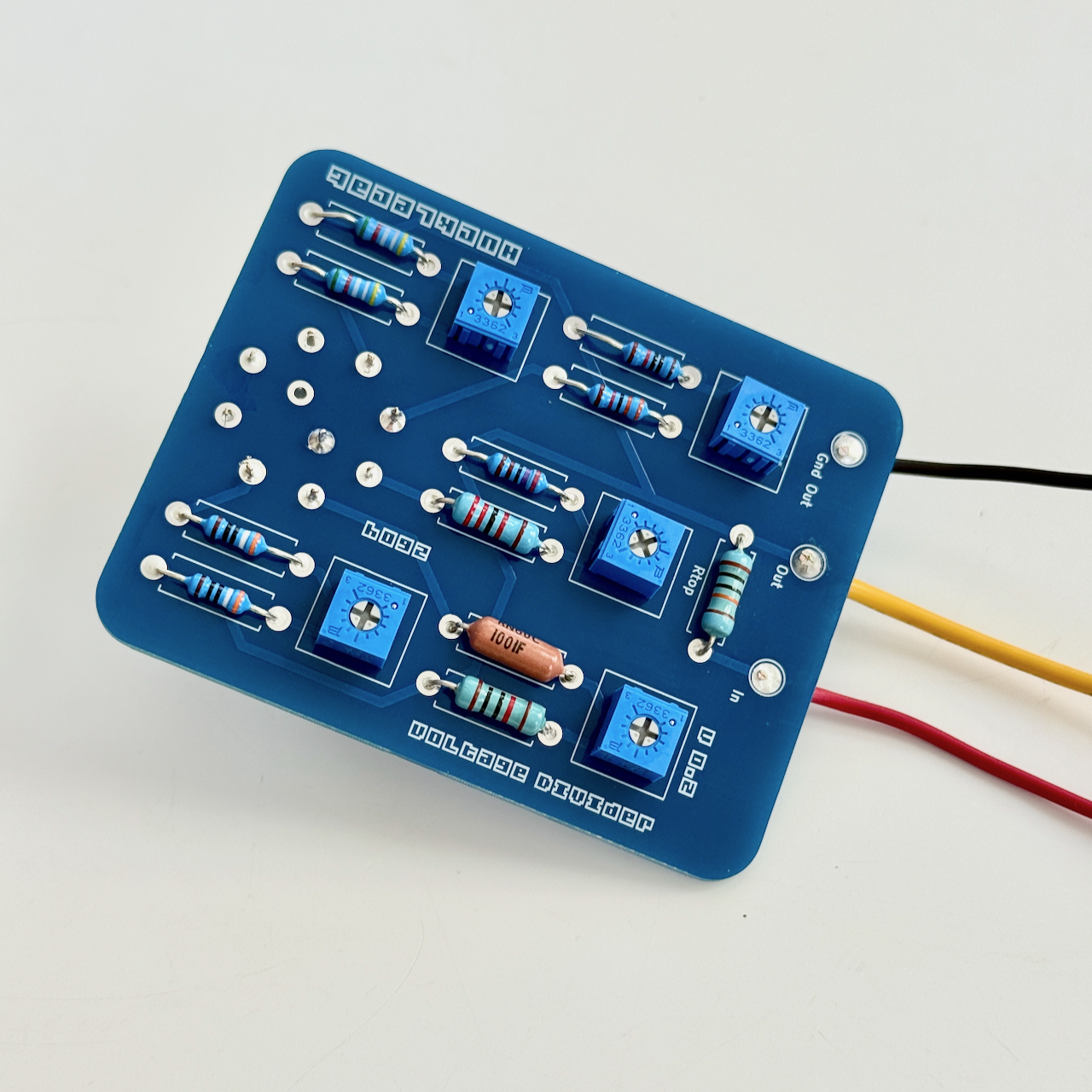
There are five taps on the PCB. Each tap on the PCB has space for two resistors and a trim pot (Bourns 3362).
Each tap is a two-resistance voltage divider:
Vin ── Rtop ──┬── Vout
              |
            Rbottom
              |
             GND
Rtop is a fixed value for all taps. (I used 100k.)
Rbottom is implemented as:
This arrangement allows:
The rotary switch selects which divider output is routed to the output jack.
The fundamental voltage divider relationship is:
Vout = Vin * (Rbottom / (Rtop + Rbottom))To design a divider for a desired ratio:
k = Vout / VinSolve for the shunt resistor:
Rbottom = (k / (1 - k)) * RtopExact values matter. Let's say Rtop = 100,468 Ω.
| Divider ratio | Vout (from 10V) | Rbottom (ideal) |
|---|---|---|
| 0.5 | 5.0 V | 100,468 Ω |
| 0.3 | 3.0 V | 43,058 Ω |
| 0.2 | 2.0 V | 25,120 Ω |
| 0.1 | 1.0 V | 11,163 Ω |
| 0.01 | 0.1 V | 1,015 Ω |
In practice, these are realized using nearby standard values plus the trim pot to dial in the exact ratio.
You can, of course, use whatever ratios you like.
The PCB is designed around a 1-pole 5-position (using 1P/8-pos form factor) like the one available from pedal parts supplier Love My Switches or PedalPCB.
The PCB is also designed to fit within a standard 125B aluminum enclosure with room to install your choice of inputs and outputs (banana jacks, RCA, etc.).
Populate fixed resistors first
Install the trimmer (Bourns 3362)
Install jumpers or series resistors
Clean the PCB
Trim each divider
Final assembly
This design is intentionally simple, adjustable, and reproducible.
Switchable Voltage Divider PCB © 2026 by Terrence Dorsey
is licensed under Creative Commons Attribution-ShareAlike 4.0 International


| Qty | Value | Footprint | References |
|---|---|---|---|
| 10 | R_US | project_library:R_Axial_DIN0411_L9.9mm_D3.6mm_P12.70mm_Horizontal | R1, R2, R3, R4, R5, R6, R7, R8, R9, R10 |
| 5 | Trim | Potentiometer_THT:Potentiometer_Bourns_3386P_Vertical | RV1, RV2, RV3, RV4, RV5 |
| 3 | Conn_01x01_Pin | project_library:Pin_D1.3mm_L11.0mm_LooseFit | Gnd Out, In, Out |
| 1 | R Top | project_library:R_Axial_DIN0411_L9.9mm_D3.6mm_P12.70mm_Horizontal | Rtop |
| 1 | SW_Rotary_1x8_MP | project_library:Rotary_Switch_8 | SW1 |
It measures 55 × 68.5 mm and has 2 copper layers, 1.6 mm thick.
20 parts. The full list of its parts is on this page, with links to each part's symbol and footprint where PCBKit's library has them.
From the tpdorsey/switchable-volt-divider repository on GitHub, at the commit this page was made from: the board is voltdivider.kicad_pcb and its schematic voltdivider.kicad_sch. PCBKit opens the board in the browser, with nothing to install.
Its repository states no licence, so its author keeps all rights: ask tpdorsey before reusing the design.


atopile/atopile
Design circuit boards with code! ✨ Get software-like design reuse 🚀, validation, version control and collaboration in hardware; starting with electronics ⚡️

davidphilipbarr/Sweep
Sweep - a small promicro based keyboard inspired by the Ferris.

rusefi/rusefi
rusefi - GPL internal combustion engine control unit

hoglet67/RGBtoHDMI
Bare-metal Raspberry Pi project that provides pixel-perfect sampling of Retro Computer RGB/YUV video and conversion to HDMI

hackclub/OnBoard
💡 Join 1,000 teenagers and make your first PCB with a $100 grant!

FreeYourStream/freedeck-hardware
all the stuff you need to build your own FreeDeck