2 layers100 × 50 mm
Chrismettal ESP Hiro ESP Hiro
punkfab/pcb-corpus
235 real KiCad boards from open-source hardware repositories, prepared as a placement and routing benchmark
102 parts1
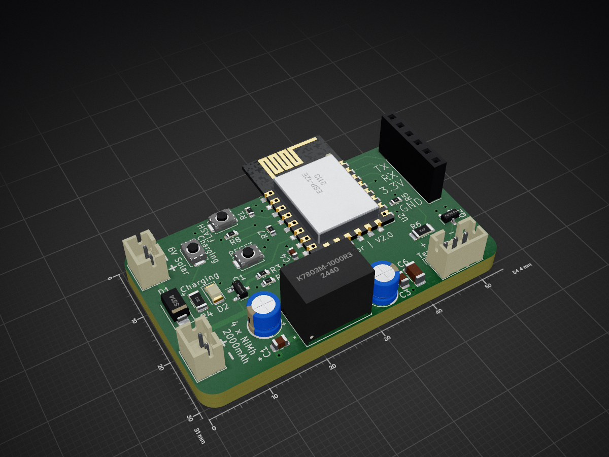
 tpanajott/PoolMonitor4
A pool monitor with accompaning PCB
PoolMonitor is an open-source printed circuit board by tpanajott, from the tpanajott/PoolMonitor repository on GitHub. It is a 4-layer board of 54.4 × 31 mm with 28 parts on 29 nets, routed with 117 tracks and 21 vias.
It is built around the ESP-12E, K7803M-1000R3 and AO3400A, with the DMP2225L-7-VB and SS14 among its other parts. Its parts include 8 resistors, 7 capacitors, 3 connectors, 2 ICs and 2 diodes. It belongs with the ESP8266 boards of this library.


This is a small PCB made to monitor the temperature of a pool using a DS18B20 waterproof sensor. The PCB is based around a ESP-12 module that will connect to WiFi periodically (period time configurable) and report the temperature together with battery voltage via MQTT. In between the meassurements, the sensors are turned off to save battery.
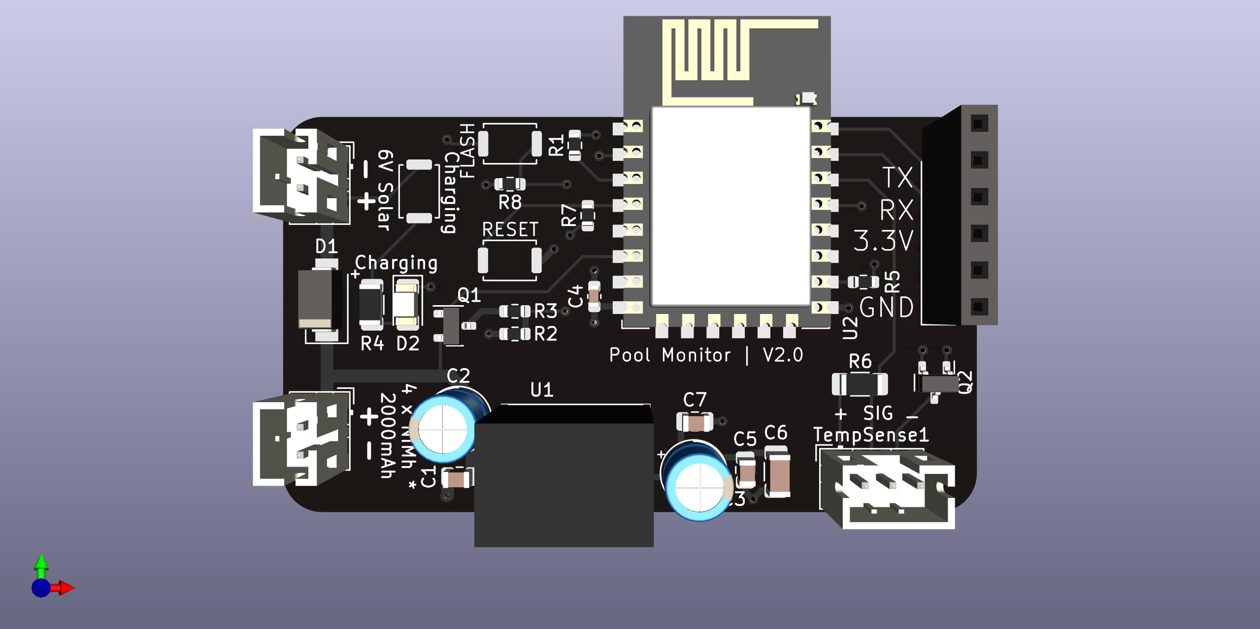
I had the board manufactured at JLCPCB. Simply upload the ZIP-file in the PCB/gerbers directory to their website. The following PCB stackup is used:
| Layer | Name |
|---|---|
| L1(Top Layer) | PoolMonitor-F_Cu.gtl |
| L2(Inner Layer1) | PoolMonitor-GND.g2 |
| L3(Inner Layer2) | PoolMonitor-3_3V.g3 |
| L4(Bottom Layer) | PoolMonitor-B_Cu.gbl |
A BOM for the project is available in the file PCB/PoolMonitor.csv. The parts list have references to LCSC part numbers.
This board is designed to use a simple DS18B20 sensor with three wires. The following wiring diagram is to be used and the sensor should be connected to the TempSense1 connector.
| Wire Color | Connection |
|---|---|
| Red | + |
| Black | - |
| Yellow | D |
This jumber, when briged, will disable the polarity protection on the power input.
This jumber will, when briged, disable to power control of the DS18B20 sensor when not reading from it. By default the power to the DS18B20 sensor will only be turned on while reading data from it in an attempt to conserve power.
settings.h.settings.h file.The following configuration example can be added to the sensor section in your Home Assistant configuration. The expire_after paramater set to 4200 means that Home Assistant will consider the value old if 70 minutes has passed since last update from sensor. This value may need to be changed in order to reflect your configuration of the SLEEP_TIME paramater in the settings.h file.
- platform: mqtt
  device_class: temperature
  name: "Pool temperature"
  state_topic: "/pool/temp/"
  unit_of_measurement: "°C"
  expire_after: 4200
- platform: mqtt
  device_class: temperature
  name: "Pool sensor voltage"
  state_topic: "/pool/voltage/"
  unit_of_measurement: "V"
expire_after: 4200| Qty | Value | Footprint | References |
|---|---|---|---|
| 4 | 10K | Resistor_SMD:R_0603_1608Metric | R1, R3, R7, R8 |
| 3 | SW_Push | Button_Switch_SMD:SW_Push_SPST_NO_Alps_SKRK | CHK_CHARGE1, SW_FLASH1, SW_RESET1 |
| 2 | 10uF | Capacitor_SMD:C_0805_2012Metric | C1, C5 |
| 2 | 22uF | Capacitor_THT:CP_Radial_D5.0mm_P2.00mm | C2, C3 |
| 1 | 100nF | Capacitor_SMD:C_0805_2012Metric | C7 |
| 1 | 10k | Resistor_SMD:R_0603_1608Metric | R5 |
| 1 | 1K | Resistor_SMD:R_1206_3216Metric | R4 |
| 1 | 1uf | Capacitor_SMD:C_0603_1608Metric | C4 |
| 1 | 2K | Resistor_SMD:R_0603_1608Metric | R2 |
| 1 | 4.7uF | Capacitor_SMD:C_1206_3216Metric | C6 |
| 1 | 4k7 | Resistor_SMD:R_1206_3216Metric_Pad1.30x1.75mm_HandSolder | R6 |
| 1 | AO3400A | Package_TO_SOT_SMD:SOT-23 | Q2 |
| 1 | Conn_01x02_Male | Connector_JST:JST_PH_B2B-PH-K_1x02_P2.00mm_Vertical | J1 |
| 1 | Conn_01x03_Male | Connector_JST:JST_PH_B3B-PH-K_1x03_P2.00mm_Vertical | TempSense1 |
| 1 | Conn_01x06_Female | Connector_PinSocket_2.54mm:PinSocket_1x06_P2.54mm_Vertical | J2 |
| 1 | DMP2225L-7 | Package_TO_SOT_SMD:SOT-23 | Q1 |
| 1 | ESP-12E | RF_Module:ESP-12E | U2 |
| 1 | K7803M-1000R3 | CustomFootprints:CONV_K7803M-1000R3 | U1 |
| 1 | LED_GREEN | LED_SMD:LED_1206_3216Metric | D2 |
| 1 | SS14 | Diode_SMD:D_SMA | D1 |
| 1 | SolarPanel6V | Connector_JST:JST_PH_B2B-PH-K_1x02_P2.00mm_Vertical | J3 |
It measures 54.4 × 31 mm and has 4 copper layers, 3.66 mm thick.
28 parts, built around the ESP-12E, K7803M-1000R3, AO3400A and DMP2225L-7-VB. The full list of its parts is on this page, with links to each part's symbol and footprint where PCBKit's library has them.
From the tpanajott/PoolMonitor repository on GitHub, at the commit this page was made from: the board is PCB/PoolMonitor.kicad_pcb and its schematic PCB/PoolMonitor.kicad_sch. PCBKit opens the board in the browser, with nothing to install.
Its repository states no licence, so its author keeps all rights: ask tpanajott before reusing the design.
punkfab/pcb-corpus
235 real KiCad boards from open-source hardware repositories, prepared as a placement and routing benchmark

CCHS-Melbourne/ESPlant
Environmental Sensor Plant - solar WiFi gardening/meteorological sensor using ESP8266

daumemo/DIY-ESP-12E-LED-Strip-Controller-4-Channel
DIY LEd Strip Controller with ESP-12E


BoltzRnD/SmartPrintCoreH7x
STM32H7 based Robust and Open Source 3D Printer Mainboard